http://www.ozvalveamps.org/ava100/ava100atxpsu.html |
Created: 18/10/2006 |
Last update: 7/06/2011
<<< OzValveAmps
|
AVA100 - ATX-style PSU's
Valve amp chassis and parts - Free!
R is for Rubbish - R is for Resource.
Contains:
- Computer power supplies as a resource
- The ATX-style supply
- What's in it for the valveamper?
- Reassembly
- PC-XT-AT style PSU's
- The Bottom Line
- Flashcaps
Computer power supplies as a resource.
If you don't have a few dead computer power supplies hanging around, then your local computer store is sure to have a few.
There are lots of computers out there. They all have power supplies, and they fail.
This means there are a lot of dead computer power supplies out there too. In most cases these will end up as landfill which, apart from ecological considerations, is a bloody waste and a shame.
So what the hell do you want with a dead computer power supply, anyway?
(to paraphrase the guy in the 'puter shop ;)
They are so cheap, complex, and internally variable, that they simply aren't worth repairing individually ('tho one Melbourne firm does production-line repair of dead monitors). Not to mention the dubious joys and excitement of working with direct-on-mains circuitry. Despite working on a lot of high-power gear I find these a bit too exciting for my taste.
Basically there are two sorts, the PC-XT-AT style, and the later ATX style. Since the ATX are now much more common and available we'll look at these first.
The ATX-style supply
We have a small sheet-metal metal box with a tail of wires and connectors.
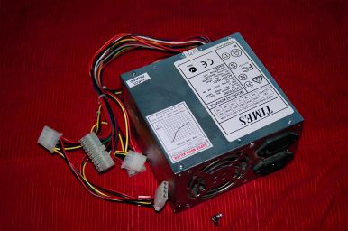
Note the exploded electrolytic cap that fell out!
The box is generally 6in wide, 3.5in high, 5.5.in deep (150w, 85h, 140d) in the form of interlocking C's and held together with four small countersunk screws.
On one face there is a fan and mains connections. These vary a little but mainly consist of an EIA input, EIA output, a voltage selector switch, and sometimes a mains switch.
Before we take the lid off we note that it has been sealed with a sticker which tells them, and us, if someone has already been inside.
We break the seal and remove the lid, and what have we got?
Normally a furry mess.
It will be filthy, full of dust, dead insects, and other crap, and more like the innards of a vacuume cleaner than a power supply. There may even be the remains of parts floating about inside. Looks worthless and only fit for the bin. Well it isn't.

A 98%-working power supply (the 2% upper-right)
Main caps at bottom with yellow sticker
It's an interesting resource to the electronic tinkerer. Which is us, right?
What's in it for the valve amper?
The most obvious is the tail consisting of about 30 by one foot plus of medium-duty hookup wire in useful assorted colours.
There are the EIA connectors, the input one in particular.
We can see the fan, and most of these are okay and still have quite a bit of life left in them.
And of course we have the case, most of which are fairly solid and well ventillated.
After we clean up the inside a bit with brushes and workshop vacuume cleaner we see a busy printed circuit board that is the supply itself.
Here things get very variable in the detail, but the general idea is always the same - mains rectifier, power oscillator, transformer, low-voltage rectifier/filter, and some control electronics for on/standby, soft-start, regulation, and overload protection.
The mains rectifier is of particular interest and generally consists of a bridge rectifier in a four-lead single case, and a couple of high value, high voltage, (originally) low-ESR, electrolytic caps.
There are also a number of other interesting components for other electronic projects or just tinkering.
Naturally we must remember that we are dealing with a unit that has failed for some reason and that something, some component, is not right. Sometimes we find the whole supply blown to hell by a lightning strike.
But I have a pile of working high voltage, high current FET's and transistors, opto-couplers, 780x regulators, line filters, and lots of other good stuff recovered from dead power supplies.
I've used recovered opto-couplers in soundcard-to-MIDI adaptors.
I've rewound filter inductors for use in mains filters and used recovered FET's exploring different (non-SCR) lighting control circuits.
Reassembly
Perhaps the most obvious thing to do is modify the SMPS to produce the voltage(s) you want, such as for battery charging, or heater and HT for a valve amp.
Both of these have been done, but they represent major and somewhat risky projects in themselves. In the end you still have a SMPS and all the risks (shock and electrical noise) that they imply.
Another option is to use the case as a basis for a different type of power supply, one more conventional to valve amps - a mains isolation transformer, then mains frequency rectify and filter.
Another possible use is as a chassis for the amplifier itself.
PC-XT-AT style PSU's
These are generally similar but a fair bit bigger, and may come in irregularly-shaped cases. These often had a massive mains switch on one side, and larger diameter fans.
A hunking mains switch could be handy, as could the extra internal room, but at this age the fans will generally be more suspect.
For our purposes the switch and the extra volume are the only real differences between AT and ATX style supplies.
So I got a couple of dead ATX's from my local computer shop (and glad he was to see the back of a couple from boxes of dozens of dead ones he had accumulated in his storeroom).
So I scored two boxes, one for a power supply and the other for the amp itself.
I now have enough rectifiers and caps that I can build a voltage-multiplying power supply, and only need to buy the trannies themselves - all the rest has been given to me free.
Moreover both have a free cooling fan if I want to use it.
The wire from only one unit will provide enough suitable hookup wire for at least one whole amp, and other sundry bits like heatsinks and nuts and bolts go in the workshop junk box for 'Ron.
The Bottom Line
Shuuush... Don't tell anyone.
These PSU cases also make a good jumping-off point for a small band/theater lighting control rig, but that's a whole other project...
Flashcaps
New: 7/6/11
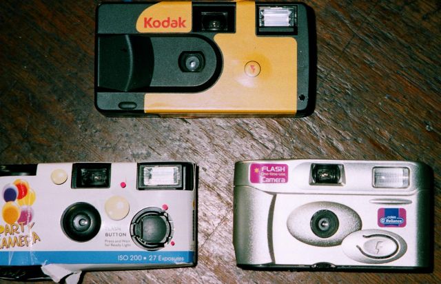
Disposable flash cameras can also be obtained from your local photo processor. You can just hit them for what is in the rubbish bin, or make an arrangement for them to save them for you, but do collect them regularly and switch them off when you've had enough.
Our primary interest here is the main flash discharge electrolytic cap. Even if the camera has been recycled many times (and they have been), all the components are still “as-new”, even the AA battery, which is our secondary interest.
These cameras come in a wide range of minor and major variants.
Getting the goodies
Honestly, a lot of this recovery is BFBI. This is a great standby job for when you need to blow off some steam.
There is typically a sticky outer lable/covering, and we need a sharp edge like an art knife to find and cut along the seam lines of the plastic case underneath.
The first one or two might be bit of a battle, but after a few you learn where to expect the seams.
Once free of the sticky, the cases themselves have plastic latches at one end, and simply snap apart. There are the odd few that have a retaining screw or two inside the film well, and this should be found and removed first.
Having cracked the case there is something very important to do before proceeding - discharge the flash cap!
Initially you will need to find the flashcap leads and short them with an insulated screwdriver. You will be surprised how many go “SPLAT!!!”.
A real shame here is that these are actually brand new high quality caps that are going straight into landfill. For this duty these caps have to have the lowest possible ESR and therefore make ideal decouping caps for preamp HT supplies.
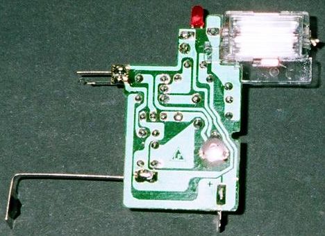
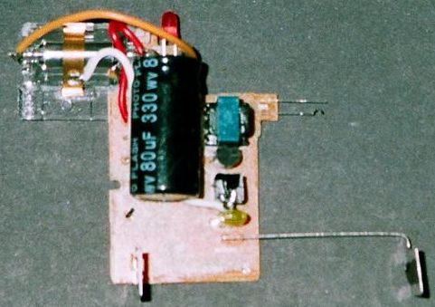
Here are some recovered flash modules. AA battery contacts, leaf shutter trigger contacts, LED or neon for charged indication, silver disc is switch contact to activate. 80uF/330V and 120uF/330V caps.
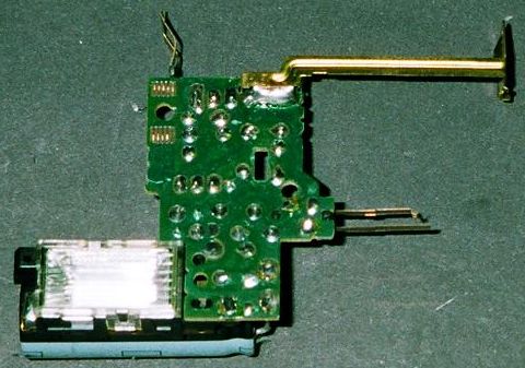
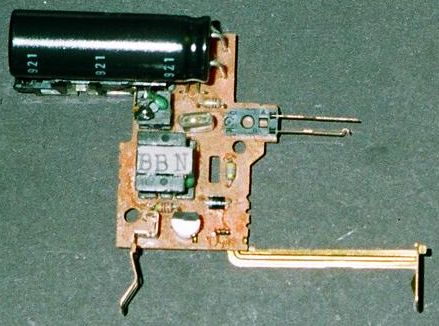
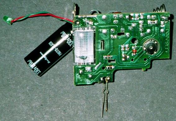
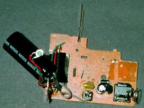
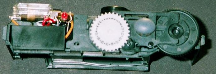
In place, above, and removed...
Other uses
Ring flash
Of course there is nothing to prevent you using these as originally intended as photo flashes.
I have (half) built a ringflash using several of these mounted between two translucent plastic salad bowls which may be the subject of another article when its finished.
HV leakage tester and Meg-ohmmeter
These little inverters produce about 300VDC. Two stacked in series with a suitable resistance to limit the available output current to 1mA (~1Megohm) and you have the makings of a high voltage tester for insulation tests on transformers and such.
A simple NE2 neon, or one recovered from a flash unit, in series with the output will provide a sensitive indictaion of leakage, and with a current meter a leakage tester that can be calibrated in megohms - a poor mans Megger.
They can also be handy where old electrolytic capacitors have to be reformed at limited current.
Safety or Disco strobe
For this application they have to flash faster, so the energy of the flash has to be reduced in proportion or the flash tube will overheat. This is best done by scaling down the capacity of the main dump capacitor in proportion to how much faster you want it to flash. You will also need to provide a trigger at the desired rate.
And they're FREE, all you have to do is ask.