Model: 1765/1767
Source: Rose Music catalogue, Peter Hutchinson
|
http://www.ozvalveamps.org/goldentone2.html | Last update:
2021/05/18
<<<OzValveAmps |
| << Goldentone index | Next page >> |
New 24/9/06
17-series, 1744, 1762, 1764, 1765, 1767
First stage circuits for above
Note (29/6/07): the following two circuits are updates to version “8 Nov 2006” to correct errors found on the previous versions. Please delete any earlier versions you may have.
Bassmaster 20 watt model 1757.
Bassmaster 40 watt model 1756.
Thanks to frequent contributor Ric of WA for this work.
[serial number table now on main Goldentone index page]
Identical to flip-top units
1765, 40W, $310
1767, 60W, $382
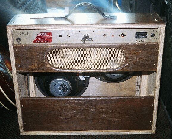
Mod: 1762
Serial: 5895
Built: 67811 - (11th August 1967?)Either stripped of its covering and refinished, or more likely in an owner-built case. Fitted with a pair of Fane 12's.
Source: Music Swop Shop
Click for full size 200k jpg Source: Melmusic |
Click for full size 67k jpg Source: Gary Kurzer |

Click for full size 35k jpg Source: Gary Kurzer |
Circuit for models 1755 and 1759. (183kb Gif. Formal circuit updated from informal tracings, 5/1/05.)
Source: David Crittle, RetrovoxHigh and low sensitivity sockets for each of the effected and normal channels. On some units the individual 1M input resistors were replaced with a single 470k at the grid.
Each channel preamped then tone and volume controlled using both sections of a 12AX7 each and a passive 2-way Baxandall tone circuit.
Most of the modifications seem to be to make the reverb channel brighter and more toppy.
The reverb input is anode mixed with the reverb return before some high-pass filtering and mixing with the normal channel.
The 6GW8 pentode is a class-A driver for the reverb springline, with the triode section used as reverb recovery amp. The top-cut network on the springline output is another afterthought.
Another 12AX7 is the vibrato phase-shift oscillator and cathode current modulator for the second effected preamp stage.
Footswitching for vibrato and reverb is provided on a cast metal pendant (attached).
Another 12AX7 as the cathode coupled 'long-tailed pair' phase splitter and feedback summer.
Finally a pair of 6DQ6A's in fixed bias driving an A+R OT2700 (3k3 plate-plate) for 40W, or OT2701 (2k6 plate-plate) for 60W, output transformer with 360VDC on the centre-tap, into 7.5 ohms (40W) or 3.75 ohms (60W).
Power supply is solid state full bridge, with the screen supply taken fron a centre-tap, series inductor filter except for the screens. A+R power transformer PT2454 (40W) or PT2421 (60W) includes 40VAC bias winding.
Voltages:
- A 360V o/p stage,
- B 340V phase splitter,
- C 240V preamp,
- D 300V reverb,
- E 180V screens, Vbias -30V to -32V (40W) or -34V to -36V (60W).
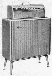
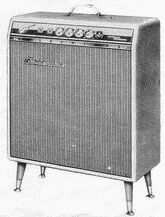
1756, 40W, $305
1760, 60W, $375
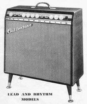
1 ch, black, shown in white 'vynex', 2x special design deluxe speakers
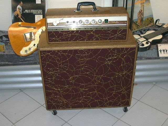
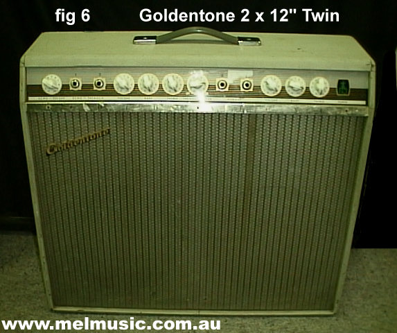
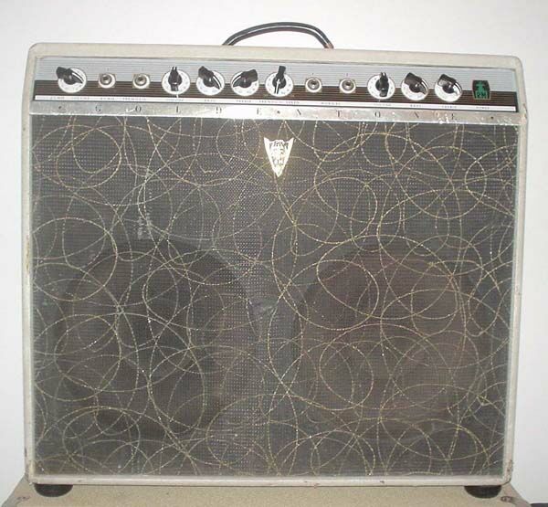
The older amp below features a flip-top plate which the head is attached to, so the head can hang inside the box for transport. The double catches are visible at each end.
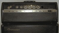
Very functional, and looks great. I just love that grill cloth. These are the original knob design with the fragile skirt, invisible pointer and faux gold inlay. More functional chickenhead knobs came later.
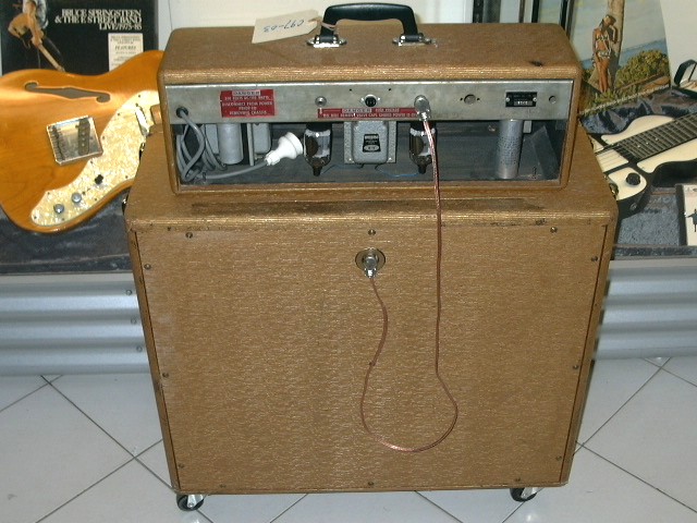
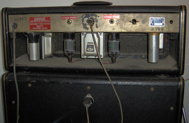
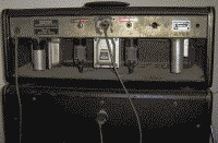
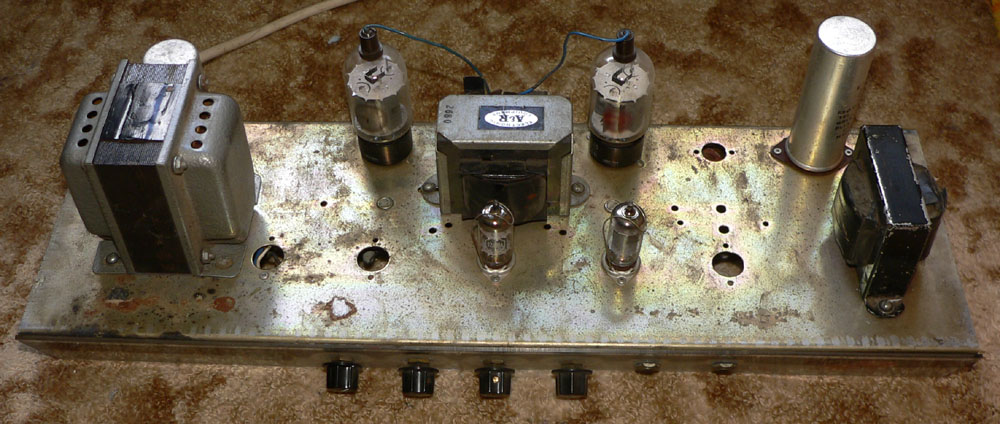
Transformer 140-0-140v @ 100mA 6.3vac @ 5A 40vac @ 15-20mA Output transformer: 3k3 p-p to 15 ohms - 40W 2k6 p-p to 15 ohms - 60WFlip-top rear seam is visible crossing behind the head. Also visible are the pair of 6DQ6A's each side of the A+R output transformer, complete with insulated top cap connectors for the anodes.
New: 13/11/09
Source: Ric
New: 2/7/06
Ric from WA has been kind enough to send a rear shot of this particular rig with the back off.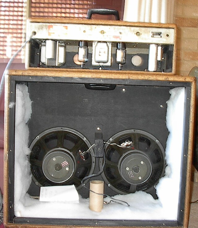
Points to note are; the carry-handle hanging inside the box; the ample sized cabinet for bass use; the space occupied by the head in the transport position; the center baffle-to-back brace to stop “balooning” of the front and back; anti-resonance padding was original; tuned vent tube in bottom.
With this last it is important that there is a breathing gap between the bottom and the floor. In the original this was provided by a set of stubby, and very cheezy-looking, screw-on legs. On this unit these have been replaced by some very practical furnature castors (not in view).
New: 2/7/06
Model: 1760
Date: 67517 - 17th May 1967
Serial: 5796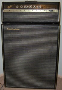
Note numbers stamped on chassis rear.Source: Jez Nazifovski
New: 28/10/09
Serial: 3920Alan Boyd writes;
I have a 1760 model going by the information on your site, 60W Goldentone Bassmaster Amplifier and would like to know if the circuit diagram is the same as the 40 watt model.
Goldentone circuits, like many amps of the era, are highly generic. Often the only difference between 40 and 60 watt models are slightly beefier transformers, and sometimes the shift from cathode bias to fixed bias, the preamps being identical.
My amplifier has serial 3920, and output transformer number 2757. It does not have a model number written on the back as shown by your site. It's probably just worn off?
It has the 6DQ6A output valves and 2 by 12UA7 preamp input valves.
12AU7's are certainly not right. As far as I know all Goldies used 12AX7's. The 12AU7 is a pin compatable double triode like the 12AX7, but with much less gain. The difference in available gain will be dramatic.
The amp almost has no volume unless the treble is turned to number 10. ... The amp does not seem to have 60 watts though of loudness when you compare it with other amps of the same size.
I have never the replaced the output valves in the 25 years that I have owned it. It has not been used for about 12 years.
This is very likely the cause. They won't be so much worried about the 12 year rest, just the 12 years hard work before that. Normally output bottles need to be replaced every year or so, depending on how often and how hard you gig your amp. 6DQ6's tend to last longer and fail more gracefully, but a few years is the best you can reasonably expect. The real worry after 12 years rest are the electrolytic caps in the power supply.
Underchassis pic. - 188kb
Source: Alan Boyd
Hi Roly, find attached a model 1764 Goldentone Bassmaster cct.(circa may 1967) which has some different values to the other ccts posted.
regards Andrew Finlay (18kb gif)
20W, $205

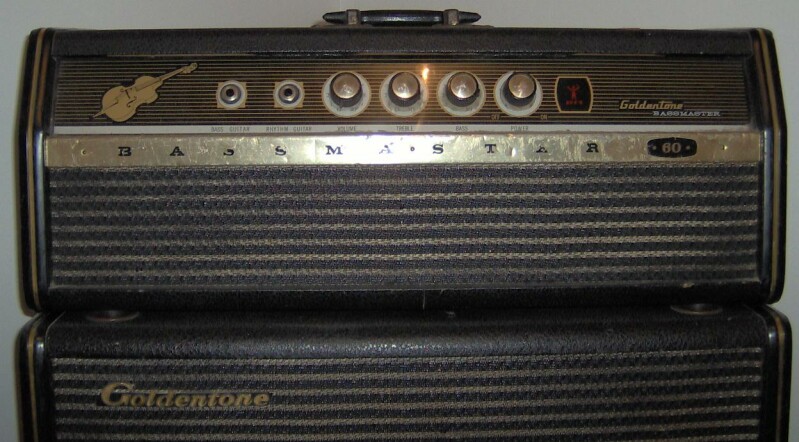
Bassmaster 30
New: 13/11/09
Serial: 4946
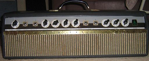
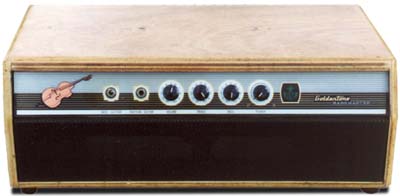
The “Solid-State” trim across the front is totally misleading, and a good example of how amps can be modded over the years to fool the unwary. This changed trim has nothing to do with the all-valve amp inside (unless you count the rectifier).
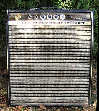
Choke 25 May 1965, power transformer A&R 2454, output A&R 2700.
Source: Peter Hutchinson
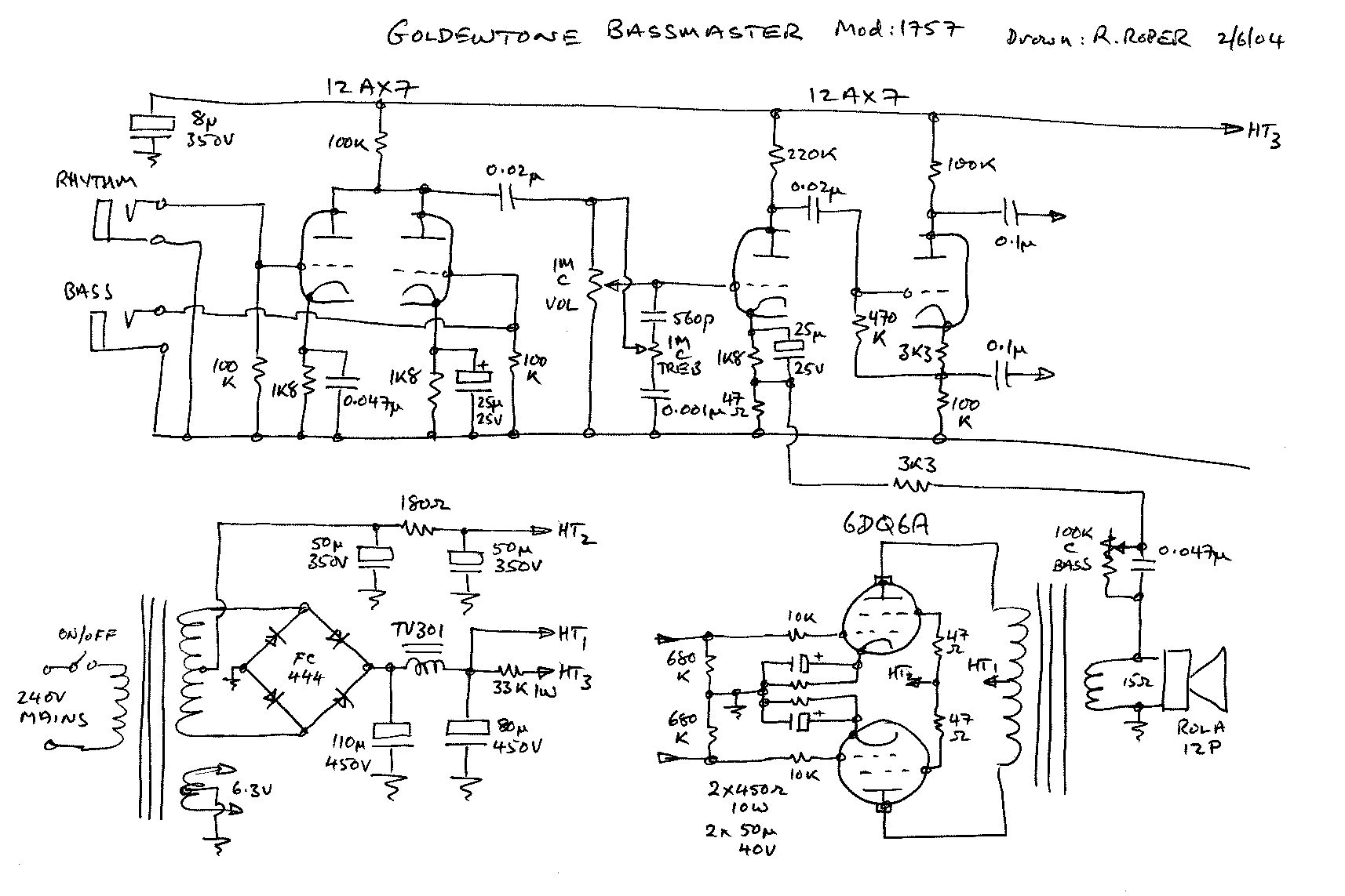
The two inputs, 'rhythm' and 'bass' are each amplified in half the first 12AX7 and anode mixed. The rhythm channel has a reduced cathode bypass to provide bass-cut.
This mix drives a fairly unconventional but simple volume and passive half-Baxandall tone control network for the treble, and bass boost applied by reducing overall feedback at low frequencies.
This is followed by another 12AX7, one half as voltage amplifier and feedback summer, the other as split-load phase inverter.
This drives a pair of cathode-biassed 6DQ6A's to a single Rola 12P 15 ohm speaker.
The power supply is a full wave solid state bridge with series inductor filter, the screen supply taken from the transformer centre tap.
Model: 1757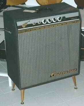
Source: Ric's Vintage Guitars
New: 05/11/06 from Aussie Guitar Gear Heads forum.
from: threefish
Subject: Goldentone Bassmaster - tips for modding for guitar?
October 19, 2006, 02:38:42 AM
threefish
So, my question is: I'd like suggestions as to where to start with getting more treble out of it.The circuit under discussion;
http://ozvalveamps.org/goldentone/1757bassmaster.jpgthinline
As for the input on the rhythm stage, you could mod it to the standard 68k/1M if your not happy with the current setup.threefish
I did some work over the weekend on the amp. First I put a small cap across the volume pot, ... I think it was about 120pF. Anyway, that made a bit of difference at theThis is effectively in parallel with the top half of the treble network. The main reason for using a top-coupling cap like this is to maintain highs at low volume settings, it has lessening effect as the volume is advanced. (see below)
threefish
removed the 100k resistor to ground, and inserted in it's place a 1M resistor, along with a 68k in series. Looking at other Goldentone schems I had seen 47k used as this series resistor here instead, but I didn't have any 47k's handy. This improvement in impedance made a noticeable difference. There's definitely more sparkle there.This is one of the most minimal input forms. You can bump this up to half a meg and stay on the datasheet, but there is really no practical reason here not to use a meg as you've done. With a passive guitar the amp input impedance makes quite a big difference to the resonant behavour of the pickup itself, and IMO 1meg is really the minimum. See figs showing p/u response v. input R;
http://ozvalveamps.org/pickups.htm
If you always use a stomp etc., between the guitar and the amp its input impedance is a non-issue (but now the stomp's isn't).
The function of the (47/56/68/what-K-are-we-overstocked-in?) series resistor is as an RF “stopper” (ditto the 10k's on the o/p grids), so it's value is not at all critical, but it becomes more needed as the input impedance rises and becomes a better antenna.
A few ferrite beads slipped over the input line would no doubt do the same job. With serious RF break-through problems (such as AM modulators in Ham shacks, under the antenna) then a small cap of between 47pF and 470pF grid to ground will shut it up, but you shouldn't need that if your connectors are clean and your cable screens intact.
threefish
When I almost max the treble pot, it sounds good. My next tinker will be with the .022uF coupling cap after the first stage. I have a .01 cap handy that while probably won't make a huge difference, may bring it closer to what I'm after.In the ECAP sim this actually doesn't make a lot of difference, some; but the following shunt treble network is working against you.
But you could do your own NFB stunt around the output. A 100r and 1.5uF in series, across the 47r in the phase splitter should brighten it up a bit.
threefish
Something else I should mention is that I experimented with mostly covering the rear opening of the cab. Experimenting with this in the past with other amps I've heard for myself how this changes the sound, and in this case it tightened up the sound considerably. It does take the slightest edge off of the other brightening mods that I've done, but I think it will be worth it in this case.Blocking the vent will raise the driver resonant frequency, and it's a generally a good idea to clunk the amp response about Fo to avoid sub-sonic speaker damage.
pete
That treble pot is a “C” taper, meaning it's reverse audio/log taper. I'm buggered if I know where you'd get one those from these days.....Well, actually no; it means I drafted the original of this cct back in prehistory before the letter codes for pots changed. In this case “C” was a *normal* log pot. “A” was linear. In those days I think and anti-log was a “D” (and there were log-log and others). These are all standard log-taper or audio-taper pots.
threefish
the feedback path? (or can anyone else?) I've had a look at this setup, and I don't quite understand what's going on, particularly with the small value cap in a “Bass” circuit.It's a normal NFB loop except that they have added a frequency-selective network. This is NOT the normal arrangement of a small “phasing cap” across the NFB series resistor. Once you cut this cap you effectively open the NFB loop (unless the bass control is down the shorted end). (That'll give you “tone”! ;)
To set the output stage for flattest (or native) response the 0.047uF in series with the NFB loop should be SHORTED. The simplest way to do this is set the bass control to minimum. Now you have a conventional valve amp with some NFB. The effect of progressively adding in the capacitance as you advance the bass control is that the NFB is then *reduced* towards lower frequencies, less braking, and thus is boosted in the forward path.
This is actually a curious thing to do in a *bass* amp as it also reduces the amp output impedance and speaker electrical damping, and most bass player seem to favor the iron grip of solid-state.
There is little point in playing around with the coupling caps after the phase-inverter since the action of the NFB loop will be to fight against you and minimise your changes.
Apart from upping the input Z so your guitar p/u can “breathe”, which you've done, a prime place to mess around is the value of the 0.047uF cathode by-pass.
In all these cases remember the corner frequency is given by;
Fc = 1/(2 π C R)
0.047uF//1k8 - cathode rhythm
25uF//1k8 - cathode bass
0.022uF/1M//1M - coupling, vol, treb
Fc C R 1881.2 4.70E-08 1.80E+03 rhythm cathode 3.5367 2.50E-05 1.80E+03 bass cathode 14.468 2.20E-08 5.00E+05 coupling So the rhythm channel already has a fair tilt against the bass falling from the corner at almost 2kHz.
jvb
Having taken out the cap in the neg fb circuit you might want to check for very high freq oscillation using an oscilloscope. Often a cap used here is to limit ultrasonic frequency which can cause audible distortion (not the good sounding kind).A good point, however in this particular amp this isn't a stability capacitor, it's just a tone control that happens to be in the feedback loop (and so operates in the reverse sense to a network in the forward path, what it *cuts*, gets *boosted* in the output, less brake rather than more accelerator).
When the bass control is at minimum we have a simple NFB divider (3k3/47r) with no phasing cap across the series 3k3. That's not to say it mightn't be better for having one; hi-fi's normally had them but guitar amps it was more like 50/50, possibly due to the lower levels of NFB normally used.
These “bass/rhythm” Goldies always sounded a bit “woofy”, but I'm not at all sure you are tackling the right end of it.
Is it the amp, or speaker/cab?
I've just run a series of ECAP sims on this tonestack, anode to grid. My first thought that all the tops where being drained off by the shunt treble control isn't right.
In fact as original and set v5t5 it already has a corner at 1kHz, well above guitar fundamentals, falling to about -8dB in the two decades to 10Hz, but flat from 1kHz to over 10kHz.
The effect of adding a 120pF top-coupling cap across the volume control top to wiper is to make this rising characeristic continue at about the same upward slope to 10kHz.
(this isn't accounting for the 2kHz high-pass corner in the rhythm pre cathode, adding an even steeper slope).
Minimum treble, v5t0, naturally produces a steep loss above about 2kHz.
Full treble boost, v5t10, produces a steep drop below about 2kHz for a decade, but it then flattens to basically flat down to 30-odd Hz, then falling again. So while this maintains the guitar fundamental it also extends well into the bass, so it doesn't actually produce much bass cut.
Now I have found that when you have to start cranking in extremes of EQ, something ELSE is wrong, and that it's better to find and fix that first.
If you are not going to play bass through it, the normal expedient would be to simply remove the back for open-back operation. I'd actually make up a minimalist back to retain physical strength and provide the speaker with a bit of protection, but mainly open.
You can give the amp frequency response an upward tilt, but if the box can't reproduce it you are only heating up the voicecoils. Your real answer might be to add a low-reach treble horn in a “top-box”.
My advice is to restore the amp to original, and try it with the back off, and driving as many other cabs as you can find to hook up and test.
Related topic; http://ozvalveamps.org/repairs/cube40.htm
Cheers,
-Roly
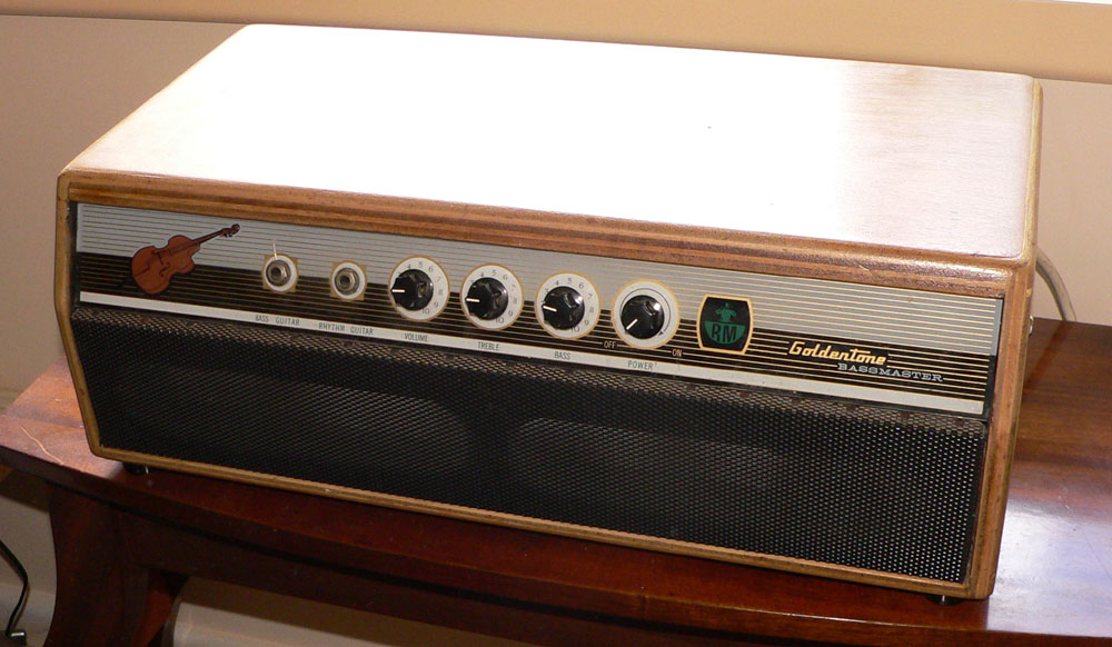
Nice recovery. A head ultimately created from someone unknown's abandoned botched attempt to de-Combio-ise an old unit.
New: 19/12/10 Ken Stone writes;
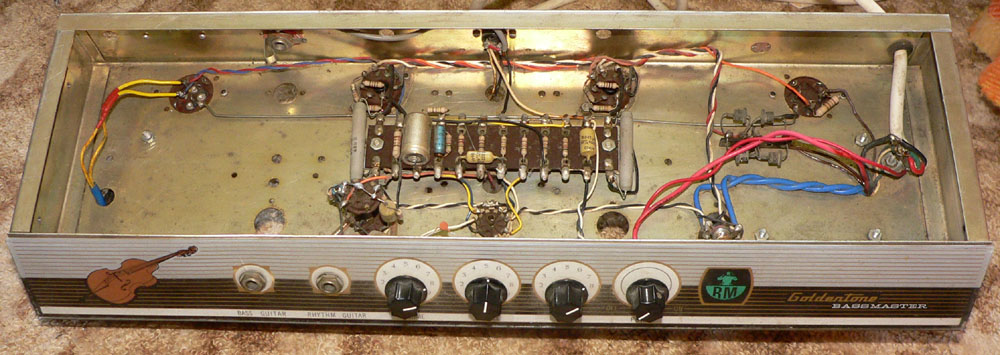
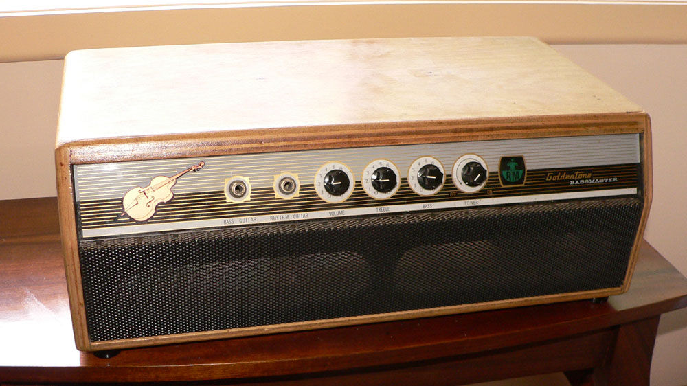
Rose Morris Goldentone Bassmaster
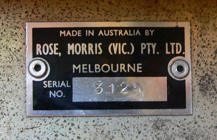
Serial number 3125 stamped on a Made in Melbourne plate.I found this amp in the late '90s sitting at the bottom of a stack of old solid state pa amplifiers at a garage sale down the road.
When I found the amp, it was in pretty poor shape, missing a valve, with missing and broken knobs, covered in glue because the tolex had been ripped off, and in the somewhat abridged form you see here.
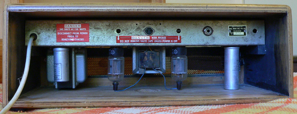
At some point in its life, a previous owner decided to turn a combo* into an amp head, cutting off the box just short of the tallest capacitor in the amplifier. The original base of the case was moved up, put on backwards, and spare bits and pieces of the case were used to fashion a crude front panel. The legs, handle and speakers were all missing. I talked the owner down to $10 for it.
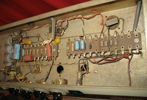
A couple of parts were replaced, including the filter choke, a valve and a capacitor in the tone control circuit. The rest of the circuitry remains original/as found.
The case was sanded back to wood, then given multiple coats of clear lacquer. The front piece of wood had two oval cutouts sawn in it, then was covered with black aluminium mesh. The knobs were replaced. Feet were attached.
I am unsure of the original model, or output power, but the smallish speaker transformer is probably a good clue. I have never traced out the circuit diagram. The original choke is long gone, thus any chance of dating it is also gone.
No obvious bias supply
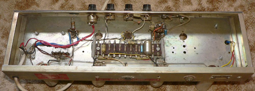
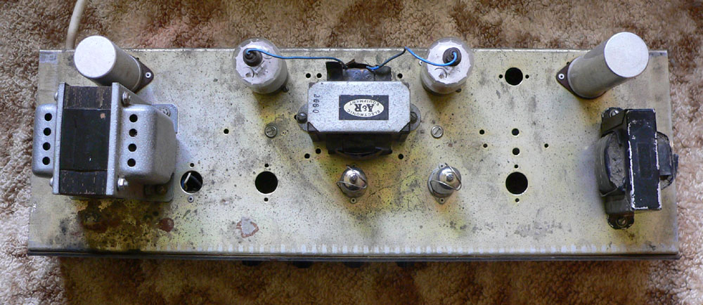
Output transformer 2680 also used in the 9-60
Source: Ken Stone
New 24/9/06
| << Goldentone index | Next page >> |
|
|