If you have oscillation the problem is how to get the feedback around the loop to a low level when it is in phase; conversely how to keep it sufficiently out of phase (negative or opposing) when the loop gain is high.
Motorboating
This is very low frequency instability at around vibrato frequencies, 1 to 10Hz.
In older amps this is almost always due to large value electrolytic capacitors 'drying out' or basically losing capacitance with age. Sometimes these can be 're-formed' but replacement is often a better option.
Other causes can be due to where, exactly, the various filter capacitors are 'grounded'. In one case intractable low frequency hum and instability was traced to a filter cap being grounded to the signal shields.
Single point earthing at the main filter capacitor isn't a new idea but it still works. Many guitar amps ignore this with many grounds to chassis all over the place, inputs, output, power supply, and others.
Daryl Mills of Logic Research wrote (23/7/04)...
I did a repair on an old Jansen lately...
You mention the capacitors dry out, very true as I measured some that the value had shifted more than 100%.
You don't mention what I found was also a culprit (the amp was motorboating and oscillating), many of the old resistors although they looked fine had also shifted in value of 50% or more and were really doing a lot of damage.
I've even kept a perfect looking 10k that measures 15% just as a 'talking point'.
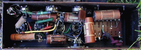
The older the resistor, the more suspect it must be. Very old 'dumbell' resistors (see Amplivox chassis pic) with wire connections wrapped around the end, using body-end-dot coding, must be checked. These are now so old that, like waxed paper caps, you should consider replacing them on sight.
Higher values, 1M and up are always suspect as these are particularly prone to drifting high. Daryl's experience shows this is not always the case, a low value going really low.
Decoupling
This is a fragment of a Goldentone 1755 power supply showing the decouping networks, so-called because they are intended to provide DC power while de-coupling the stages from each other for AC signals.
There are a couple of different ways you can look at decoupling networks depending on what you're doing.
The simplest way is that the shunt cap has to have a low reactance to signal frequencies or the stages will have a load in common to impress signals across.
Another way is as a set of low-pass CR networks which are tuned to a very low frequency well below the amplifier passband (so that when the frequency is low enough to pass the decoupling network, the amplifier gain has already dropped to a low value below its bass cut-off frequency.
If either the cap or series resistance feeding it should go low in value the filter frequency will rise, f=1/wCR, into the passband of the amplifier (where it now has gain) and a low-frequency oscillation may result. But it may produce other odd effects if the unwanted coupling is of opposing phase (see below).
A similar supply decoupling network is frequently used for the screen of pentodes in low-level stages (rare in guitar amps except possibly as the reverb driver stage) and similar considerations apply. It is not unknown for screen by-pass caps to go low or open and cause problems. “By-pass” because they shunt any signal to ground.
Supersonic
Supersonic instability can be recognised by a characteristic “thump, hiss”, and a loss of level and/or fidelity when a control, normally treble, is advanced. Below this setting everything may appear to be fine. Amps with this kind of fault, particularly solid-state ones, should not be run in this condition for more than a few seconds. You may not be able to hear it but assume that it's close to full available output power and flogging the guts out of your amp - you may even see the pilot light dim. It is particularly deadly for piezo tweeters.
This may come in the form of a solid oscillation, or more insidiously as a parasitic oscillation. This is a burst of oscillation that only occurs when the amplifier is driven, over only part of each input cycle, and possibly only at high levels.
This generally makes a subtle mess of the sound and flogs the output stage and speakers.
The only real way to investigate this is with an oscilloscope where the oscillations may appear as fuzz on signal peaks. Keep in mind that these may be high enough in frequency to be outside the passband of many cheaper “audio” CRO's. The workshop AM radio tuned off a station can sometimes give an indication of RF-oscillation in an amp.
Most valve guitar amp output stages are fitted with small RF-stopper resistors right on the grid pin, VHF-style, typically 1k5. The object is to kill the Q of the hidden VHF oscillator lurking in the black heart of each output valve. With 807's in particular the anode has to get the same “stopper” treatment or sometimes a lossy Radio Frequency Choke at the top cap.
Apart from self-oscillation within a stage, HF instability can be caused by direct capacitive coupling back to an early stage from one of the later high level stages.
After eliminating broken grounds and all by-pass caps as okay, the cure is generally adding shielding, such as (restoring lost) preamp valve cans, re-dressing underchassis wiring, changing open signal wires for shielded, even installing tinplate shielding.
Look out for added crossover networks possibly in multi-way cabs matched to a head later, or retro-fit tweeters.
Few early amps were tested on other than their intended load, generally a group of identical speakers in a direct-radiator cab. Stability may be degraded by a passive crossover.
Audio frequency
This is rare and generally due to a microphonic preamp valve (but I have just replaced a microphonic 6CA7/EL34, one of the worst cases of full-on audio feedback microphony I've seen).
It is not unknown for 'Foo' to have rewired the output connector with the feedback reversed. After replacement the phasing of an output transformer must be checked, it's not enough to assume that because it doesn't take off the NFB is corrrect. Many valve guitar amps have such low NFB that reversing it won't always result in oscillations.
The correct way to check NFB phasing is to disconnect the NFB, drive the amp very lightly, then re-connect the NFB and observe if the signal level rises (wrong) or falls (right). If you measure this reduction and express it in dB, that's your amps NFB level.
The negative feedback line often consists of a resistor with a parallel phasing capacitor. If this cap happened to fail open the amplifier stability would be reduced.