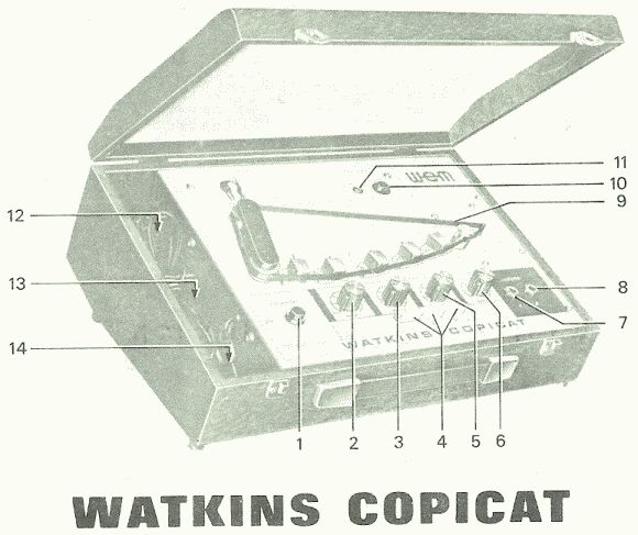
1969 Watkins Copicat (UK)(45kb jpg)
|
http://www.ozvalveamps.org/tapeecho.html | Created: 12/3/06 | Last update:
22:50 14/09/08
<<<OzValveAmps |
Contains:Tape delay units work by recording the signal on a fast moving tape loop which is then taken past a number of replay heads. Various facilities allow the choice and level of each of the signals, speed of the loop or delay time, re-recording playback to extend the echo effect, and so on.
| Tape Echo |
Full circuit (243kb gif, transistor) of the Copicat shown above
A partial block diagramme of a Moody tape echo unit, serviced sometime in the 80's (26k jpg).
12/03/06
Circuit for valve Echoplex.
General points
In Jan 2005 Ian Dittman wrote...
I have come into the possession of one of his tape echo units, its fairly complete [I think] and was wondering if there was anybody around who knows how to work on these things.
I replied with some general points about tape loop echos...
Well anyone who can cope with a valve reel-to-reel recorder should have no troubles with a tape loop delay.
The mechanics
The first point is the mechanics. And the first point of the mechanics are the tape heads. If they have 1/4-inch tracks worn in them, which is fairly likely, they will need replacement (which could be interesting, depending). This wear leads to a progressive loss of trebles until the sound is very muffled.
The second mechanical point is the tape drive, particularly the metal drive spindle. If this has been bent it will produce a strong waver or flutter, genuine vibrato, on all signals. Often the only thing to do is straighten it, and this is almost impossible once bent, even in an engineering workshop - there will always be some runout and flutter.
One home workshop method is to take the flywheel/capstan (they are normally one part) out of the machine and try rolling the whole length of the spindle between wooden (first) or steel flats mandrels.
Some units drove the tape directly with the motor spindle (since the exact tape speed is unimportant - you aren't going to try and play the loop back on another machine ;). Since this is normally a common induction motor (used in turntables, blow heaters, fans, etc) and it may be much easier just to replace the whole motor if required.
If it's belt drive old belts turn to tarry goo. This has to be cleaned off (metho and elbowgrease, toluene works better - if you have a fume cupboard available, it's carcinogenic) but a wide range of belts are available from places like WES Components (wescompnents.com) in Sydney. Rollers too.
Pinch rollers
The rubber pinch roller should have a light 'crown', and definitely not a small step above and below where the tape runs. The metal spindle doesn't directly drive the tape; it drives the rubber pinch roller either side of the tape and then the pinch roller actually drives the tape. As a result the pinch wears down either side of the tape, leaving a raised land under the tape run, and eventually starts slipping.
The slight crown serves to keep the tape running in the middle of the tape path and loss of the crown can cause the tape to wander sideways. Excessive tape supply tension will do the same, although this problem is generally confined to machines with cartrage loops, not short ones.
There are still many roller assemblies out there and a bit of cunning finding a suitable roller may be required (eg the last one I did in 1846 I had to carefully extract a suitable roller from an arm intended for a different machine, but this is generally not a major problem).
Bias oscillator and erase
Sorry, but I have to get a bit techie here. Another key question is what style of circuit it used, the 'economical' version being of dubious value when new, and doubly dubious for actual work these days. [Moody loops do seem to have a bias oscillator] Cheaper machines used DC recording bias and erase. Everybody else used AC bias. The difference is in manufacturing costs and sound quality.
Simply impressing the signal on the tape works, but is subject to high distortion due to tape magnetics. In the 1930's Telefunken engineers in Germany applied a high level supersonic bias signal with the record signal and defeated the distortion mechanism. Cheaper machines used DC (or no) bias for record, and a magnet for erase. This works sorta, but produces high tape hiss.
Since the AC erase signal was pinched from the record bias oscillator, a small magnet somewhere along the tape infeed is a sure sign there is no bias oscillator. The lack of a magnet, however, doesn't prove it has AC bias since some manufacturers passed DC through a head to make to appear to be the real thing, but economised on the actual oscillator stage where the user can't see. :(
Worth repair?
With the more basic units the real question is generally mechanical - is it simply worn out (heads, guides, spindle bearings, &c)? If so I doubt it is worth the effort (or in your case, cost). However if it's in reasonable nick and not seriously damaged or bent it should be possible and worth the effort, but it'll never be any better than it was new and that might not have been so hot.
The key point really is head wear. If they have obvious slots the width of the tape, or a trapazoidal wear pattern, beware. Run your fingernail across the tape head face (ie top-to-bottom). It should feel smooth with no obvious nicks or steps to catch your nail. Some wear, a small step down and up again, is to be expected, but a trench that stops your nail is a bad sign.
Tape
The best kind of tape to use for loops is a black Fe tape with a carbon backing as used in “Que-masters” and other cartrage-type endless loops in radio stations. (the tape has to be slippery 'cause it's drawn out sideways from the middle of the loose reel). The tech at a community radio station might be a good bet for a few metres in an old cart (or a box full if they've gone digital).
The splice cut should be across the tape at a slant angle (most reel-to-reel manuals show you how to do it). In tape loops is is commom to make this more slanted than normal, say 45 degrees, to hold down the inevitable thump as it passes the heads. The Roland unit had a big cart of tape like the Que-Master so it only went thump every couple of minutes, rather than seconds.
Ordinary Fe tape can be used, but it tends to shed oxide needing more frequent replacement and head cleaning. DON'T use Chrome Cr, CrO2, Fe-Cr, “Metal” or such tape in a loop machine - it's HIGHLY abrasive, about ten times more than Fe tape (and you actually get slightly better results using a real angle-grinder on your heads).
Tape record/replay electronics are a bit more exotic than guitar amps, but any tech worth their salt should have no real problems.
-rr
|
|