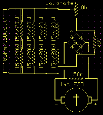
When you work on amplifiers you need a dummy load to take the place of the loudspeakers.
If you doubt that just try it for a while, and if you don't agree now I'm sure that those around you (even if you live in the Gobi desert) will convince you.
One reason is that you want to be able to listen to the amp chassis itself for audible clues during testing.
There isn't a lot to be said about a dummy load.
It's a bunch of power resistors mounted somehow so that you can connect easily and they can get hot harmlessly.
This suggests a metal rather than plastic case, and good ventilation.
It needs typical connectors such as a 6.5mm socket and XLR male and/or any other connectors you encounter like “speak-on”.
I also have a set of binding posts which double for wire connections and as somewhere to sample the signal for the test instrument.
The output power can then be calculated using;
P = E2 / RWhere; P is power in watts |
As a result you find yourself stabbing “25.4 times times equals divide 8 equals” into your bench calculator a lot.
So a very handy addition to a dummy load is a wattmeter.
A full-on wattmeter is quite a device, measuring voltage and current and accounting for phase differences for accurate power measurement. There is also a device called a Bolometer that measures RF power by heating effect.
But if you are dealing with a fixed, resistive, load as we are with an amplifer, then a square-law voltmeter can be calibrated to read directly in watts on a normal linear-scale meter.
As it happens, for low voltages the turn-on characteristic of a germanium diode is a square-law.
Initially, and up to a point, the current through the diode rises as the square of the applied voltage across it.
As simple as it is, this makes a surprisingly accurate linear-scale wattmeter.

Connect and bring out the mid-points for 4 ohm work
Calibrated at 50 watts mine is still better than 5% at 10 and 100 watts.
I don't take it too literally in the threshold below 10 watts, but it's still pretty good.
The rectifier bridge is four OA81 germanium diodes but it shouldn't be critical and you might find that the e-b junction of germanium transistors salvaged from an old radio could be pressed into service.
I was also lucky enough to score a 270-degree scale 1mA meter which makes accurate readings easy.
“Are these supposed to glow red-hot?” asked Al as I got a bit carried away with a 400-watt rack amp.
An inviting addition would be a cooling fan driven by a rectifier and regulator connected across just one of the load resistors.
A possible alternative indicator is to use a logarithmic Line-of-Light LED display driver LM3915 powered like the fan.
If I built it again I'd make these changes;
- more watts, say 400
- self-powered fan
- high-low range on wattmeter
- 50 ohm wirewound pot and jack to drive monitor speaker
Wattmeter inspired by reader idea in Wireless World c1972