Operation
Layout
Construction
Testing
Packaging
I'm none too impressed with the whine of cooling fans that seem to intrude everywhere these days.
During breaks in band practices the roar of the rack amp cooling fan is always intrusive enough for somebody to get up and turn it off.
Ideally all such fans would only run as fast as they needed to at that moment.
Circuit
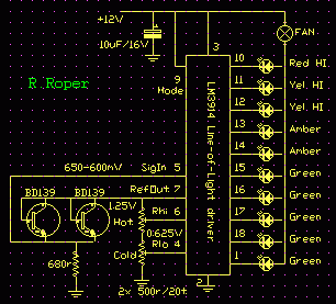
The LM3914 is a line-of-light LED driver which lights up to ten LEDs in linear proportion to an input voltage.
It also provides a stable reference voltage.
To avoid the need for individual limiting resistors in series with each LED the chip designers cunningly made each output a programmable current sink.
What this means is that the amount of current each output will pass can be set (programmed) with a resistor, and that the outputs will vary in voltage to keep the set current flowing.
The chip has two display modes;
- dot mode, where only one LED lights at a time, and
- bar mode where the LEDs light progressively until all are on.
In bar mode the LED supply current varies from zero to ten times the set current for one LED.
But because they are current sinks they are quite insensitive to variations in voltage on the LED supply rail.

This allows us to supply the LEDs via a voltage-dropping load, in this case a 12 volt DC fan drawing around 120mA.
Operation
As either of the two temperature sense transistors heat up its B-E voltage drop gets smaller, starting at about 650mV at 25 degrees C and falling by about 2mV for every degree rise.
When the transistors are cold the voltage across the 680 ohm resistor is equal to Rlo so all the LEDs are off and the fan stopped.
As the temperature rises so does the voltage on SigIn and LEDs progressively light drawing current through the fan.
Four or five LEDs are enough to start the fan and after it has started the speed is controlled over almost the full range from just puttering over to full blast.
The sensor types are not at all critical and any silicon diode or transistor that is physically useful should work.
I only used BD139's because they were to hand, would jam into the transformer, and bolt to the heatsink easily. They must remain electrically isolated however.
More sensors can be added in parallel but it is wise to measure the actual B-E voltages cold, and match them as much as possible.Layout

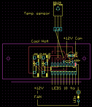
Mainly you need to have reasonable access to the two adjusting trim pots.
Construction
Just a quicky on dab board for an amp rebuild.
Testing
Before you wire them in, set both pots to half way using your ohm meter.
With the sensors at 25 degrees set the Cold trimmer so that the first LED lights.
Heat the sensor to 50 degrees, or whatever temperature you have chosen, and set the Hot trimmer until all ten LEDs light.
Repeat until done.
Packaging
Mounted on stand-offs in the bottom of the amp case.