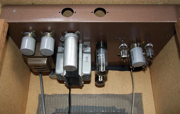
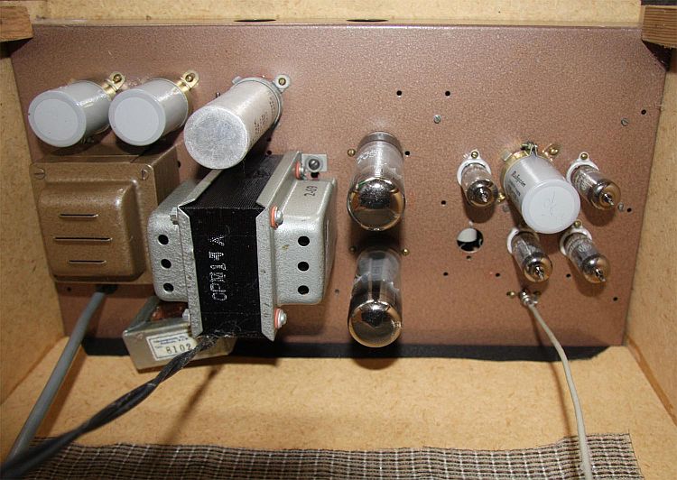
Underchassis detail 330kb jpg.
|
http://www.ozvalveamps.org/ace.html | Created: 24/12/10 | Last update:
19:39 5/06/11
<<< OzValveAmps |
(was Sonata.htm)
Manufactured by A.C.E. Radio, Sydney
136 Victoria Rd,
Marrickville, Sydney
New: 5/6/11
Thanks to Tim Robbins;
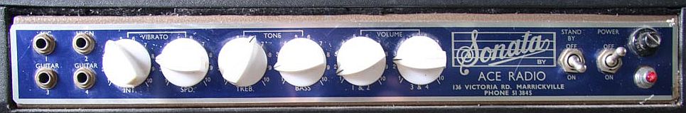
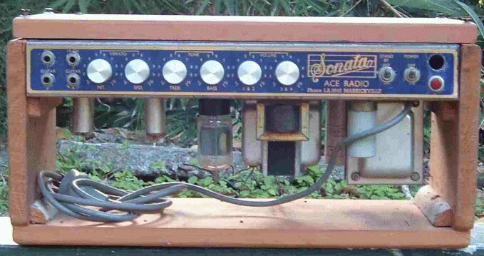
These have a general front panel similarity to the Chandler.
New: 24/12/10
hey roly,
Inputs and controls: 4 inputs, guitar 1, guitar 2, high, mic. Vibrato intensity, Vibrato speed, Tone treble, Tone for bass, Volume for 1 + 2, Volume for 3 + 4
Valve types used: 4 6BL8 s + 2 6CA7 s
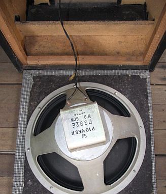
Rated output power: speaker is rated at 60 watts so im guessing around 40 watts
Effects (if any): vibrato, not working, as footswitch appears to be broken, on playing i thought i could hear some but the dials didn't seem to do anything
Other facilities (e.g. line out): footswitch, appears to be broken
Price, history, etc: i bought it off of a guy who bought it at a rural auction for a deceased estate.
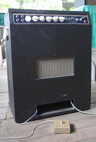
the speaker is a 15 inch alnico pioneer, the same one that is in a MAXIM bass amp on grouse guitars, it sounds to me like it has a pretty good range, but it produces a lot of rattle in the old box.
i included an extra large picture of the circuit in case there is any clues about the amp hidden in the detail.
I have a couple of queries about this amp that i would like to ask if you have the time, the amp has a significant audible hum on all channels, and a high level of weird distortion, do you think a simple replacement of valves would fix this, or is the problem probably something else?
do you think it looks like all the main components are original, i read somewhere that the playmaster 112 uses 6BL8 s, do you have any experience with these, what do you think of the valve set up?
is it possible that the four inputs are biased for different instruments, like bass, guitar and microphone, also, what does high refer to, high gain or suited to a high pitched instrument?
how would i go about trying to trouble shoot the vibrato, is there a valve i can replace or should i try to fix the footswitch first?
thanks for your time,
it is greatly appreciated, ozvalveamps is awesome.llewellyn
Source: Llewellyn Millhouse
Llewellyn,
thank you for writing, and for the pix of the Sonata. Ace is one of those marques that seem to have all but vanished, yet they were regular advertisers in the old Radio, TV & Hobbies mag. Did a lot of jobbing chassis work for RTV&H kits if I recall.
lm> Valve types used 4 6BL8 s + 2 6CA7 s
Now this doesn't sound right.
lm> Transformer numbers 3 ( i think )
More likely a power transformer (the biggest), an output transformer, and an HT smoothing choke (transformer-like, but small and only has two wires).
A pair of EL34/6CA7's are capable of 60 or more watts, but much more comfortable around 40, and this would be typical of builds of this era.
The effects may still not work after the effects footswitch is repaired, but they *certainly* won't until it is.
lm> it produces a lot of rattle in the old box.
Even new, many guitar boxes could do with improvement. No shame in adding a bit of internal bracing to stop the "accompanyment" of a rattling cab. A classic retrofit is to put a padded brace between the centre of the back (of a sealed enclosure) and the centre of the baffle (with two speakers) or to the speaker magnet or dust cap with a single speaker) to pre-stress the front and back out a little and take up play that allows rattles. In many cases a bit of woodworking glue and tightening some internal screws can work wonders. Beefing up corner/edge bracing can help, the aim being *rigidity*.
Second order stuff includes adding edgeways skew braces to large panel areas to stop them "drumskinning". Even with open-back and vented enclosures they should still be airtight around the rest of the cab, and cabinet *rigidity* is the watchword.
Now, purely off the top of my head (wearing my tech's hat), ALL 6BL8's - this CERTAINLY doesn't sound right. It MIGHT be, but it would make it a unique amp in Aussie design history.
The almost universal arrangement for all stage amps of the period is one-to-several 12AX7 9-pin twin triode preamps, MAYBE a lone 6BL8 as tonestack recovery amp (pentode secion) and phase-splitter/driver (triode section) for the output pair. (see AVA-Playmaster 116/7 circuit for typical application).
The 6BL8 itself is a fine little bottle, another 9-pin orginally from the scanning circuits of b/w TV's, it got used a bit in audio because it was dirt common and cheap, and is a poor man's half-12AX7 triode, and half EF86-similar pentode.
But with valves, just because it "plugs in" does not mean it's going to work!
It is most unlikely, however, that this amp is bottle as the maker intended, and simply getting the right bottles in may move you forward considerable (I'm thinking your tremolo here - the wrong valve will kill a trem oscillator stone dead.)
The only real truth is to be found in the wiring in the underchassis - which bottle has it been *wired* for, 6BL8, or 12AX7? Getting this right is an essential first step, and some (many? most? all?) of your other problems may well come clean when this is sorted out (being only symptoms, not faults in their own right - 'tho they still might turn out to be).
> is it possible that the four inputs are biased for different instruments, like bass, guitar and microphone, also, what does high refer to, high gain or suited to a high pitched instrument?
Again, if you have a look at the optional inputs on the PM117 cct you will see, I think, something very similar to what you will find around your input sockets under that shield. It's anybodies guess really because this was an area of considerable "creativity", but we can bet that the pairs are "high" and "low" (generally meaning "level", but equally could be "gain"), and between a fairly flat hi/lo, and "conditioned" inputs. These coulkd be treble boosted for guitar, treble cut for bass, or even both at the same sensitivity.
Almost all valve guitar amp circuitry is blindfold-dumb stuff, but with inputs and tonestacks you have to pay careful attention because this is where designers got creative.
Underchassis (with everything dead, unplugged, good light, securely propped) take a really good look around the input and first stage valve base. The PM117 circuit shows the pinout (from below, clockwise from gap) of both the 6BL8 and a 12AU7 (a typical 9-pin triode). You will need the pinout of the 6BL8 and 12A?7 group from AVA or some other valve data site (see AVA links page), and compare what you've got with both pinouts to see which one makes sense.
My suspicion is that (at least) three of these 6BL8's should be 12AX7's, and it could even be all of them.
Again, using the PM117 cct for the general structure, follow the signals back from the output valve grids to the driver/PI stage. This stage is the most likely to actually need a 6BL8, so you need to trace this base underside too. It's Sydney to a brick it's inout will come from the wiper of the main volume control.
This is a key point because this is where you can initially cut the amp in half, and determine if your problems originate before (preamp) or after (power amp) {or both, power supply} there.
It's the logical place to inject, sample, and observe signals. {A tape deck line in/out is a handy way to sample preamp signals (e.g. driven from a CD player or FM radio, and monitor on headphones), and inject a signal to test just the power amp (and supply) and speaker.
In old amps if no other cause is obvious, then hum normally comes from the electrolytic caps in the power supply chain having aged and lost capacity. These are a simple retrofit with a bit of soldering and attention to polarity.
- fix the vib/trem footswitch. Should be more mechanical than electronic, and will get you started.
- have a go at tracing-by-comparing-with-PM117 the input and first valve circuit; trace it no matter how rough, scan and send to me. If you can't read resistor colour codes, not to worry, you will only be dealing with perhaps a dozen different values and will quickly come to recognise the common ones without thinking.
- you may actually find it easier to start with the output/PI trace since that is likely to be simpler and more straightforward.
The first stage is to be sure we have the right glass in the right sockets. Depending on what we find (above), we need to then move on to the distortion and vibrato problems as separate problems (if they haven't already solvced themselves).
Let's know what you find.
{If you don't have a small soldering iron and resin-cored electronic solder, some hand tools, and a basic yellow DVM ono, you're going to need them.}
Cheers,
-Roly
Adrian Mengede wrote (23/09/06)...
My brother recently picked up a Sonata head at a recent suburban brisbane garage sale (cost $1) and I checked your site to find out a bit about it. I noticed you don't have any photos so while this one has seen much better days you might find it useful for your site until a better example comes along. I'm currently tracing the cct so I'll send that when it's finished too.
The empty hole was most likely for a 3AG mains fuse holder.

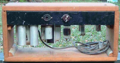
The empty octal socket will be the output to the speaker, similar to some Goldentones. The plugged socket will be to select the required output transformer tap, suggestive if a Playmaster circuit.
Looks like it may be very similar to a Goldentone or Playmaster 116 or 117 of the era.
|
|
