|
http://www.ozvalveamps.org/ava100pre.html | Created: 21/10/06 | Last update:
22:00 05/07/08
<<< OzValveAmps |
![]()
![]() Caution: (Oct '06) At this stage the AVA100-Series exists only on paper and is not a finialised design but a work in progress and as such may contain significant errors.
Caution: (Oct '06) At this stage the AVA100-Series exists only on paper and is not a finialised design but a work in progress and as such may contain significant errors.
A simple front-end with heaps of gain and radical single-knob tone control.
After spending a lot of time analysing this circuit I'm already having second thoughts about the order of the stages; but we can shunt stages around and if we are careful the numbers will still be valid.
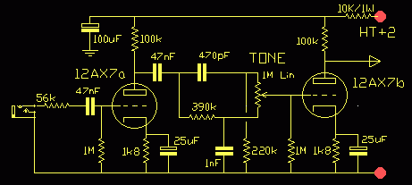
Preamp, tonestack, and postamp, (then via volume to main amp).Preamp
This is very conventional, straight off the data sheet and most classic Aussie valve amps. The anode resistor can be anywhere from 47k to 220k, and some people say that the sound of the stage gets warmer and less metalic from low to high. I'm skeptical, but it's an area open to tweeking and experimentation.
I made a fairly arbitary selection of a 100k load on historical precedent and the desire to keep the stage output impedance lowish.
This is its simulated response...
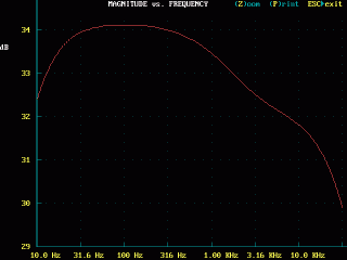
Note carefully the offset dB scale, and that the stage is really quite flat
within a couple of dB across our bandwith of interest.EQ - Tonestack
Tonestack is a much better name than EQ for equalisation (of response) because guitarists use their tone controls to radically shape their amplifier bandpass, not smooth it out flat.
When you think of single-knob tone controls the first thing that comes to mind is the simple top-cut control. This surface illustrates the action of a simple top-cut control.
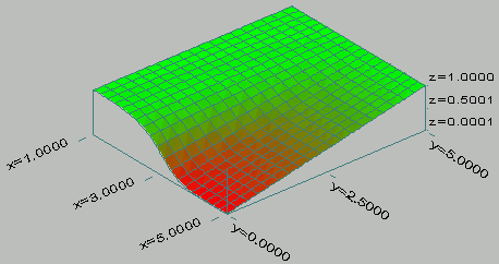
x = log10(freq), (freq = 101 = 10Hz to 105 = 100kHz)
y = pot rotation CCW to CW,
z = response (attenuation in red)It's easy to make things complicated, and if a Fender three-knob tonestack lights you up then by all means use that. But I was looking for something that would give a bit of a mid-scoop in a single knob.
And thanks to Duncan's Tone Stack Calculator, I found what they call the Big Muff - “The Big Muff tone stack is a simple hi/lo tone control suggested by Jack Orman. This type of sweeping control is common in FX units.”.
[strictly speaking a “sweepable” control is one with a user-settable hinge or corner frequency (ωc or fc), such as a parametric, and this one certainly isn't.]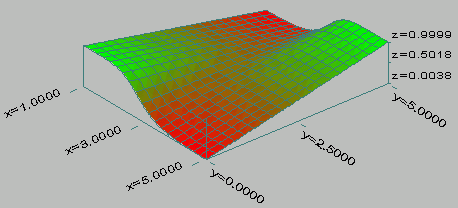
Big Muff tonestack - twice the effect
x = log10(freq), (freq = 101 = 10Hz to 105 = 100kHz)
y = pot rotation CCW to CW,
z = response (attenuation in red)
(Generated in SurfX3D - Surface Explorer 3D)The mid-band scoop can be seen above as the depression right in the middle, along the x = 3 or 1kHz line, and around y = 2.5 for pot near the middle.
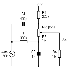
From Duncan's TSC.The values have been scaled to suit the Zsrc = 50k ohm source impedance of our valve stage. For correct operation filters must be driven from impedances much lower than the elements, typically 10:1 lower.
This is a simple network consisting of two parts, a high pass or lead network consisting of the C1-400pF and R2-220k, and a low pass or lag network consisting of the R1-390k and C2-1nF.
These are connected to opposite ends of the tone pot so it ranges from low-pass to high-pass. This should provide much more variation than available in the top-cut control which would be the other single-knob contender.
And certainly in the computer it seems to...
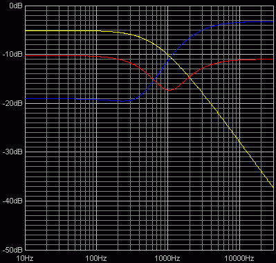
Tonestack Response - red = mid (5), yellow = full bass (0), blue = full treble (10)We can see that set to the mid-point (red line) it has a considerable mid-band “scoop” or dip in response. In concept this is the same as a loudspeaker crossover network, except here the high and low pass elements have been deliberately tuned to leave a bit of a hole in the crossover response.
As it happens the extreme curves also map the two networks, so the blue line maps the R1-400pF and R2-220k high-pass and the yellow line the R1-390k and C2-1nF low pass. [for 400pF use 390pF Styroseal]
By tweeking the values of these four components, two resistors and two caps, we can tweek the reponse how we like. We can reduce or even reverse the scoop into a lift by bringing the two networks closer in frequency so they overlap more, or deeper by tuning them apart more.
We can move our whole scoop and hinge point up or down in frequency by tuning both networks up or down together.
The key is...
Xc = 1/2 π f C
thus
Fc = 1/2 π R C“At the angular frequency ω = ωo = 1/RC, the capacitive reactance 1/ωC equals the resistance R.” and “when ω = ωo = 1/RC, the gain = 1/200.5 = 0.707. A signal with frequency f = fo = 1/2 π RC is attenuated by 3 dB”
For fully-worked examples see School of Physics, The University of New South Wales[here “ ω ” or “omega” means angular rotation in radians per second. This is simply the normal frequency in Hertzes and degrees of phase, expressed instead in radians. ω = 2 π f. ωo is the corner frequency.]
Filter design can be a real Black Art and some of the worst math I have encountered has been around filters. Thankfully most guitar amp tonestacks are fairly simple, but there are still the effects of control interactions, and non-ideal source and load impedances.
If you want to invent new arrangements then you will need a circuit modeler of some sort, but if you want to fiddle specifically with guitar amp tonestacks Duncan's Tone Stack Calculator is essential. It's free for the downloading and allows you to change values and plot all the popular types, Fender, Vox, Marshal, and some others. Within its limitation of application it does a really great job quickly even on slow iron under Win95.
Apart from being very useful and suited to the reality of the task, it's also great fun and instructive about how frequency-dependant networks behave without a π or ω to be seen anywhere. This is one simulator that really is a substitute for sitting at the bench birdsnesting components.
Post amp
This is simply a repeat of the preamp.
Originally this was to be followed by a single volume control and then into the main amp VAS.
Here is a set of reponse curves across the whole amplifier at each stage, preamp to speaker, tone at mid-point, gain controls maximum. All gains total progressive, with respect to the baseline 0dB input level.
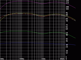
dB gain over the inputBlue - pre anode, Green - post anode, L.Blue - VAS anode, Red - PI anode, Violet - o/p anodes, Yellow - speaker
The initial idea with a single volume control between the Post amp and VAS...
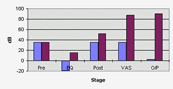
Gain profile with EQ in the middle.The revised idea, a gain control between Pre and Post amps, then EQ, then a master volume...
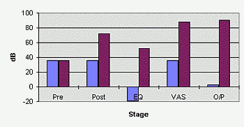
Gain profile with EQ after Post/crunch stage.
Then it occured to me that this second stage would most likely be the stage to clip under overdrive, and that the tonestack was before there in the signal chain. Have I followed Hi-Fi thinking here out of habit without due consideration for overdrive?
With a gain or overdrive control between Pre and Post amps the guitarists should be able to set the amp for anywhere between clean and shred front end, to control the tone of that shred in the following EQ stage, and use the master volume to get that shred at bedroom studio levels.
Or the gain can be set down and the master turned up for classic power amp overdrive.
Since the tone input can be controlled to some extent by the guitar itself, its tone setting, pickup selection, and your playing style, it seemed to make more sense to have the tonestack after the overdriven stage so that the tonality of the overdrive could also be controlled.
If this turns out to be a wrong guess it is still a fairly easy matter to rewire the blocks to place the tonestack pretty much anywhere you like in the signal chain.
And the same is true for level controls, call them “trim”, “drive”, “gain”, or “master”.
So the current stage lineup goes like this;
Input - Pre - Gain control - Post/crunch - tonestack - VAS - Master vol - PI/main
Can I use a different tonestack?
By all means. Any of the common valve amp networks should substitute without any problems. Fender stacks tend to have more insertion loss, while Marshal stacks tend to have less than the Big Muff. But since this front end should have gain to burn, it shouldn't be a problem.
|
|