Initial transformer positioning
|
http://www.ozvalveamps.org/ava100/ava106redroaster.html | Created: 15/10/10 | Last update:
2021/05/18
<<< OzValveAmps |
Geoffro from the Hunter documented his Lamington-II build as he went in a thread on AGGH.
New: 15/10/10
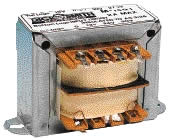
I got 2 M1991 Transformers from tricky dickies (*) on Friday arvo, for $12.99 each. I got 1 MM2002 from jaycar but returned it for a MM2004 2A Transformer. I still have to get the M1130 output tranny, should be ordering it next week. I also picked up my tin, it is a roasting tin, 40cm x 28cm x 6cm. $19.00 from GO-LO.
* Dick Smith Electronics have discontinued stocking all electronic components, but similar transformers are available from other suppliers such as Jaycar, Altronics, Wagners, etc.


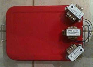
Initial transformer positioning
Darryl
The three power transformers do not have to have a particular orientation relative to one another. If your Dick Smith transformers are similar to some I used, the 240 volt primary uses tags rather than flying leads. If so, try and orientate the transformers so these tags are as inaccessible as possible, because you can't completely shroud them with heatshrink.If you do line up the three power transformers with their cores parallel, then the output transformer core should be at 90 degrees to the power transformer cores. As bulldozed says below, if the output transformer is at the far end of the chassis, coupling will not be a problem anyway.
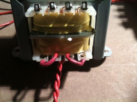
Mains connection, above
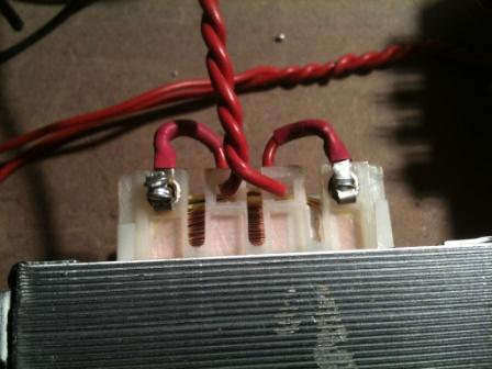
Mains connection, belowbulldozed
I've found that if you have the right width heatshrink, you can press right over the plastic mounts of the tags, covering nearly all the metal. It's about as good as you're going to get.Roly
I try to mount trannies with the mains sides together; anything not covered by heatshrink can be beefed up with silicon goo.bulldozed
it wasn't until you posted that I saw the red heatshrink over the red wire in the closeup (too well colour coordinated, or is it my eyes on the way out!!). If you double-layer heatshrink - do what you've done over the solder joint, that's fine; then fit a larger diameter over that to stretch over the 'square' nylon blocks and conceal the rivets, you'll be a bit better covered. On the outermost pairs, you can carefully trim away some of the excess nylon to make it easier to slide the tube over (as you would find with the inner pair of lugs) and make those outer lugs the same as the rest. It's more of a point on the top-most lugs, as they're most likely to get stray fingers, but a good practice to apply anyway.Geoffro
BTW, i did the headphone trick (*) on the red roaster tonight, surprising results.The funny thing was with only the 2 - 27.5v trannies hooked up, bulldozed and darryl where right, up the opposite end was nice and quiet, but when the 3rd tranny is hooked up it isn't so quiet, but i did find 1 spot.
* The “headphone trick” is used to minimise hum pickup by the ouptut transformer of stray field from the power trannies. It consists of connecting a pair of headphones to the speaker side of the output tranny, energising the power trannies, then moving the output tranny around the chassis to find the position that gives minimum him in the headphones. A recorder or mixer with VU meters can be used instead of headphones for better sensitiviy and quantitive results if desired. Take great care with this test as the power trannies will have mains voltage on their primary sides.
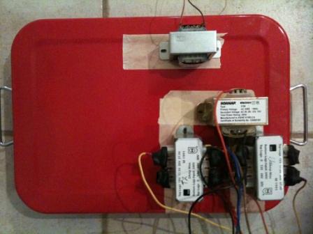
Tranny layout
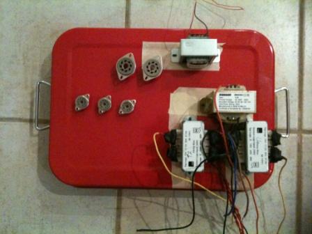
The top-left corner looks like a better position for the OPT
Geoffro
Roly, is there a way i can run 2 EL34's (6CA7's) with the M1130 O/T instead of the 6L6's???Roly
{Now why would you want to do that? Oh, never mind...
goes and looks at AVA page}6CA7 - 48W - 3.5kplate-to-plate
6CA7 - 54W - 3.5kp-p
6L6 - 55W - 5.6kp-pYum well okay, 3k5 p-p for the 6CA7 vs. 5k6 for the 6L6.
With 8 ohms on the 8 ohm tap an M-1130 gives only 2k p-p, more than a bit low, but if we put 16 ohms on the 8 ohm tap we get a more reasonable 4k p-p.; or 8 ohms on the 4 ohm tap. Take care of the valve pinouts, bang em in and fire it up, and it should produced something...
My guess is that the power ratings of the trannie are peak or similar, and that for guitar service you are going to need a pair in parallel to get to the 50Wrms level. There was a huge thread on just this a while back (on AGGH - “In The Shed”).
Geoffro
Now as to my layout, i have since done more headphone tests and you all where right, up the other end or the chassis is best.Roly
Both o/p bottles need cooling and shouldn't be too snug on each other (or anything else really) unless there is a compelling below-chassis reason.
Distance, and physical balance.Electronically the 6L6 is a better choice for guitar amps than the 6CA7. {IMNSHO}
Geoffro
do any of you guys use these terminal blocks for incoming mains power connection?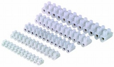
Terminal or “barrier” stripsif so what prep do you do to the wire, do you tin it or leave it stranded?
Roly
Yep, that's the sort of thing I use, and a very good question. Try to use one “right-sized” for the job, not too tight and not too open.Take care the mounting screws don't bite into the insulation too much.
I strip, twist, and double to half-length (so the insulation comes right up to the copper ferrule and the stripped wire intrudes exactly half way; always take care when tightening that the wire is actually trapped under the screw head and not riding its side loose, or any strands are astray.
Tinning is neater and a bit easier, but it is deprecated because solder cold flows and the joint loses clamp tension. (This is much more of an issue with kilowatt-up terminations).
Ideally there are little copper sleeves you can get to crimp over the strands before clamping. (Lily = gild)
Tinning does make it much harder for that errant strand that goes "SPLAT!" the first time you plug in.
This termination (tinning) may give you on-stage crackles and a red face, but it won't start a fire at this power level (the normal worry with soft connections). In this application I generally tin the wire.
What you should pay close attention to is;
- (if not removable) the power lead must be very securely anchored and protected from chafing where it enters the equipment. Well enough to pick the whole amp up by. Seriously. NO tension may be transmitted to the electrical connections. (One day your head will wind up suspended by its power lead, and you will be glad you did it properly)
- The mains safety earth must be made as securely as possible. And make your earths a bit longer so they are the last things to rip loose.
(Contrary to the above, it is mains switchboard practice to twist all your earths together, solder them all up in a giant blob, then put a large copper double-screw thimble on it, then bind it up like a terradactyl leg with green-and-yellow 'leco tape. Common practice isn't always best practice.)
geoffro
(mains cable entry) use a gland in the holeRoly
The plastic ones can be a fair cow to get in. They also work better if inserted backwards, from inside, out.I prefer boofy hard rubber gromments in the entry hole, then to a couple of bolted P-hoops to get good grip on the cable. This is partly because I like to use heavy-duty 3-core on stage gear 'caused it gets a lot of abuse, and that doesn't co-exist well with the placcy bungs (which work better with thin cable).
However, thanks to dead 'puters disconnectable (EIA) mains leads and sockets are now free for the scrounging from your local 'puter shop.
geoffro
Ok so i am a little confused about the heater wiring for the pre-amp and PI tubes, on the schematic it shows conection to pins 4 and 5, what about pin 9? do i connect to pin 9 as well as i usually would, or does this have anything to do with wiring these tubes in parallel with the 12v???Darryl
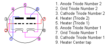
The heater rating in 12A*7 valves is 12.6 volts between pins 4 and 5. The heater centre tap is connected to pin 9. If you have a 12.6 volt heater supply, use pins 4 and 5, and ignore pin 9. If your heater supply is 6.3 volts, tie pins 4 and 5 together, connect one side of the heater supply to these pins, and the other side of the supply to pin 9.
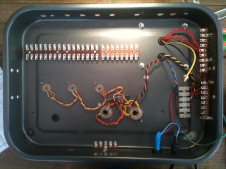
Underchassis overview
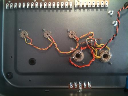
Heater wiring
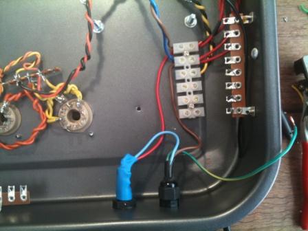
Mains wiring
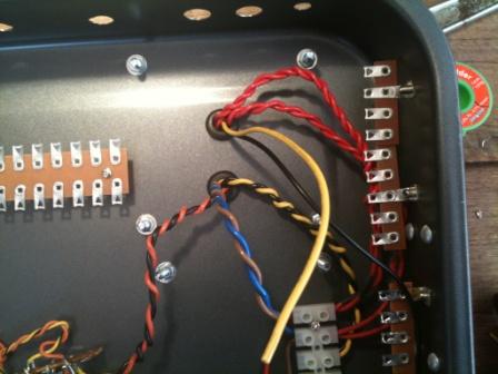
Power tranny wiring
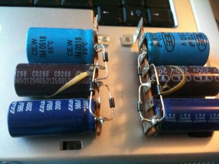
Voltage multiplier assemblies(to be continued)

Power supply circuit in PDF format - 63kb
Amp circuit in PDF format - 132kb
|
|