|
http://www.ozvalveamps.org/electravox.html | Created: 2/12/06 | Last update:
16:36 8/11/10
<<<OzValveAmps |
Manufacturer: ?
Distributor: Australian Musical Instruments
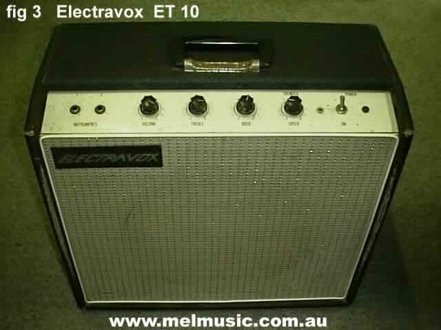
| ET8 “Escort”, ET10, BR40, BR60, G?60, Solidstate Tallboy, Mini |
New: 25/10/09
![]() Derek Lark has sent in a preamp and effects circuit tracing for an Electravox 50 head.
Derek Lark has sent in a preamp and effects circuit tracing for an Electravox 50 head.
New: 21/7/09
Serial: J7-81
This electravox, serial J7-81, was very sick, the guy wanted new caps but it needed three new valve sockets to get rid of the microphonics.
Not a good example, the reverb tank inside the back panel makes for no room to keep it all cool and he is now complaining of burning smells from the power transformer.
Shame as the two 6CA7 design with reverb is quite a nice amp. Sorry about the quality of these photos, I do have high res if anyone needs them.
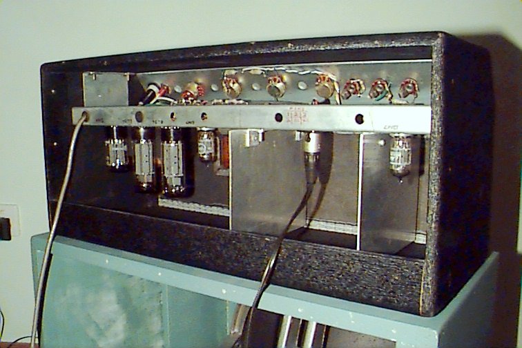
Underchassis right view, middle view, right view.
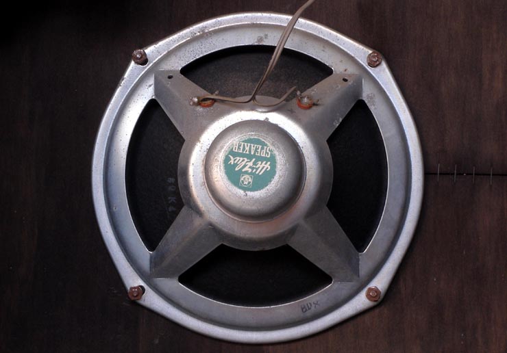
Source: Derek LarkAbout the only thing we can surmise about this one is that it's a 10 watter with a big speaker.
40 watt bass rig, 2x 6CA7/EL34's,
2 x 15's, valve rectifier.Date built: 60's?
Serial: 232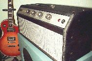
Click for full size 35kb jpgChris Arthur takes up the story...
Power Supply
The power transformer is unmarked so I don't know who manufactured it, anyway the windings are as follows:
Primary: 240VAC with no taps.
Secondaries: 330-0-330 VAC, 22 VAC, 6.3 VAC & 5 VAC.HT Rectifier is a 5AR4 (5 VAC heater), HT Filter Caps were all 25uF/500VDC, there's four all up, two in the supply and one hanging off each of the 12AX7 supply lines.
There's no choke, just a 5 Watt WW dropping resistor of around 2K2 (from memory). Bias supply is via a silicon diode (one of those early stud types that could be found in B&W TV's) and a 25uF/50VDC Filter Cap.
DC Supply outputs voltages (idle state):
HT1 = 475 VDC,
HT2 = 465 VDC, (So 10 volts across 1K/5W)
PA Bias 31 VDC
Volts @ V2 = 420 VDC (45 Volts across the 10k is 4 mA's of current)
Volts @ V1 = 375 VDC (45 Volts across the 22k is 2 mA's of current)
The original Electrolytic were made by ELNA. All other caps are those Philips axial types (rolled Mylar, with a yellowish-tan colour coating) they can be found in 1960's Oz TV's and transistor radios, etc.
All of the original valves were stamped "Miniwatt made in Australia" (the 12AX7's had a 1963 date code) and the tag strip wiring has that very Aussie technical trades look about it.
Inputs, Pre-Amp & Tone Stack
The BR40 has 3 Input jacks, are all common (via RC network) to pin 2 on V1a (12AX7) the volume control appears to be between V1a (pin 1) & V1b (pin 7) and this does show up when using the amp.

")
Click for full size 73kb jpg
Errata: bias electro should be +ve to ground.If you turn the volume right down the input noise reduces accordingly but if you vary the treble (with the volume right down) you can hear a slight tone shift, up or down, from the noise generated in V1b (fed to V2 via tone stack).
Click for full size 83kb jpg
Note interstage shieldsI must say that you need to listen attentively to hear this as the BR40 is not overly noisy, that is until V1a, the input-amp is brought back in. If the volume control was after the tone stack (as with the Moody) you wouldn't really notice this effect.
Phase Splitter & PA
Click for full size 166kb jpg
Note unused chassis holes, and pot-case “ground”.The tone stack appears to be between V1b and V2a, with V2 being a 12AX7 in long tail pair Schmidt configuration.
The output tubes (6CA7/EL34) have about 30 Volts of grid bias supplied, HT1 is around 440 - 470 VDC (load, no-load) & HT2 about 80 Volts less.
The output transformer, like the power trannie, is of unknown origin but output Impedance is both 8 and 16 Ohms (maybe 15), had to test to make sure of this.
In my opinion this particular transformer is a bit light-on for handling 40 Watts, it looks like something you would expect find in a 15 - 20 Watt Amp.
When driven hard (3/4 volume!!!) the core saturation appears to be a bit on the savage side, you start getting a fair bit of what I call “60's” Fuzz type sound!
Pix and text: Chris Arthur
His site: www.qsl.net/vk3jeg
Thanks for reminding us about Electravox Chris.
Missing circuit values: (typical)
V1a (Ik=1.1mA) rk=1k8 ck=25/25 ra=180k cc=0.1uF/450VW
vol=1Mlog (all pots log (audio) taper)
V1b (Ik=3.9mA) rk=470 ck=25/25?
Series 22k and 10k should be 1W
P.I. cc1 and cc2=0.1uF 450VW
Fuse ~0.5A standard action, ~375mA slo-blo/delay
Bias supply - caution, schematic theme only
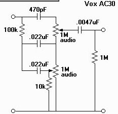
Rf=120k?, Cf=select on squarewave ringing testThis is an approximate idea of the range of the tone controls.
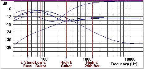
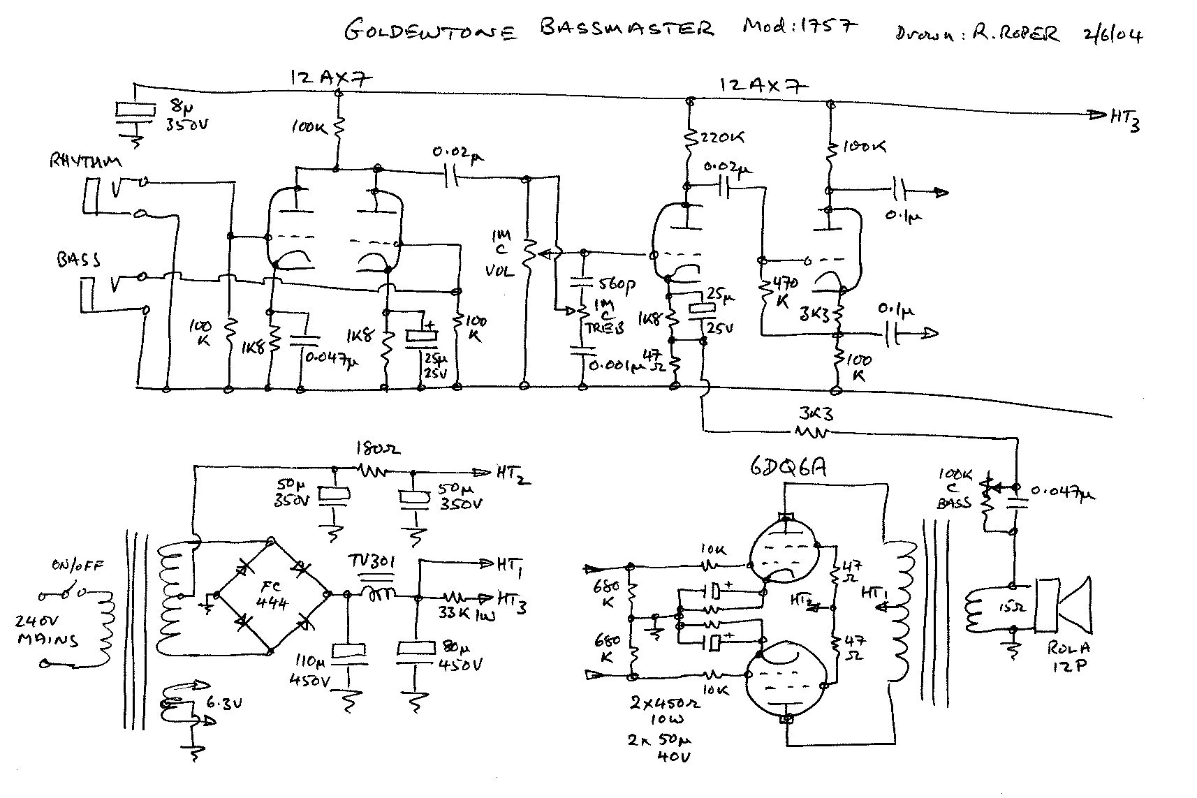
This profile is fine for guitar and maybe accordion, but somewhat lacking for bass guitar. See for example the Goldentone Bassmaster circuit.
Note this AC30 circuit differs from the Electravox, as drawn (100k position).
Some nice shots thanks to Grouse Guitars.
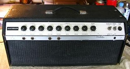
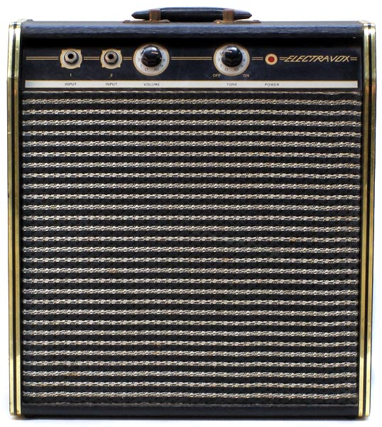
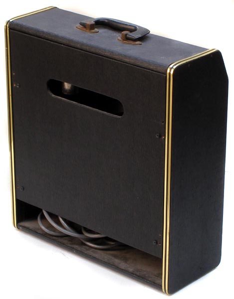
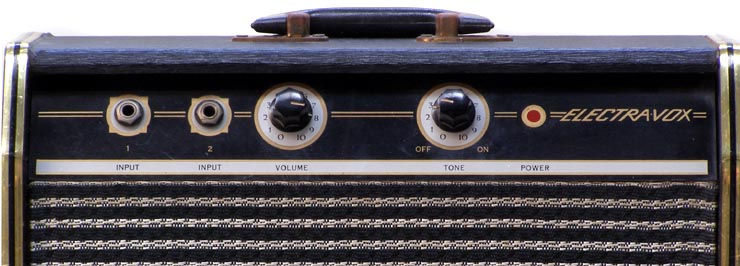
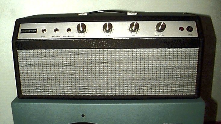
Neil Rote:Made in Melbourne Australia and distributed by Australian Music Industries Pty Ltd. This model is the BR60, and the serial number is 236. I wonder how many were produced? It is difficult to be certain about production year, but I assume '60s as it has three inputs; Bass, Rhythm and Accordion! I kid you not...
A classic valve head with 2 x EL34s (6CA7) valves in the output stage. 5AR4 valve rectifier in the power supply gives that lovely live 'squishy' feel, and 2 x 12AX7s in the pre-amp and splitter stages complete the valve lineup. All point-to-point hard wired.

This head is in fantastic condition, both electrically and cosmetically. Original tolex is in great shape with hardly any tears or nicks, and even the 'grille' in front of the amp is intact. Still has the original handle and feet that fit into corresponding wells in the matching 4x12 quadbox. The faceplate is virtually unmarked, and all the original knobs are still present.


I aquired it from a local shop (tipshop) off an eldertly gentleman who was going to dump it, I offered him $20 - DEAL!
Took it home, cleaned it up, obviously been in the garage for a long time never used, plugged it in and it WORKED, including reverb & tremolo, I even got the orig trem-rev footswitch.
I have replaced all electrolytic caps & cleaned all switches & pots so they are noise free & this amp is a gem. As far as I can tell all is original.
2ch - Normal & Vibrato
Effects, vibrato & reverb
Controls , vol, treb, bass, reverb, speed & depth
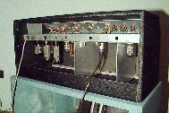
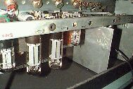
There are 4 valves in the preamp stage, 1 x 12AX7 & a 12AU7 in the preamp stage, then there is 2 more 12AX7 prob to drive the vibrato & reverb stages.
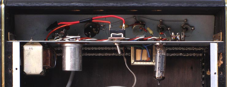
The power amp module consists of mains transformer, output transformer, phase splitter & output stage.
Phase splitter is 12AX7. The output is still 6L6GC, no bias adjustment found, pins 8 & 1 grounded.
Preamp tubes 12AX7, phase splitter 12AT7, output tubes 2x 6L6GC look original, made in USA.
Note: as usual “vibrato” here actually means tremolo or amplitude modulation. -rr
From Scott Mcardle
Hi i have been looking at your site for a little while now in seach for any info on my electravox as i have been unable to find anything about it anywere or even see a pic of one that someone else has, so im submitting these photos and hopefully you can tell me a little more about it i dont think its valve but it is vintage, its a great amp i use it as a practice amp, my mother picked it up from cashies about 10 years ago and up until recently had just been sitting around, i never used to use it because simply it doesn't have gain overdrive that kinda thing but i now have a zoom and it just sounds great, also it has a plessey c12p in the box,the tranformer has the number 0150 on it,and it turns on by turning the speed switch, I cant find a model number anywere on it. - Scottsmcrp.jpg)
smcrp.jpg)
Note reverb line, back right
smcrp.jpg)
Using a steel chassis as a heatsink only works on small amps. Adding proper heatsinking can only help.
(see Gibson repair)
Full size underchassis picture.
New: 8/11/10
![]()
Circuit for 60's single 6GW8 1x8-inch combo, thanks to J.Mumford and C.Lilly.
Zipfile containing detailed internal underchassis shots;
A single 6GW8 does all the amplifying
Looks like a retrofit mains switch to replace a failed switchpot
Source: Neil Rote
New: 8/11/10
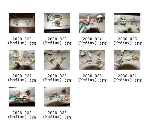
Serial: 157
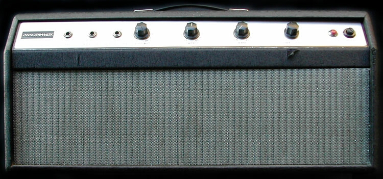
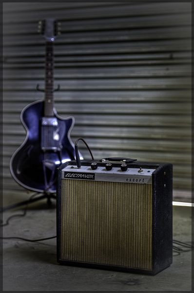
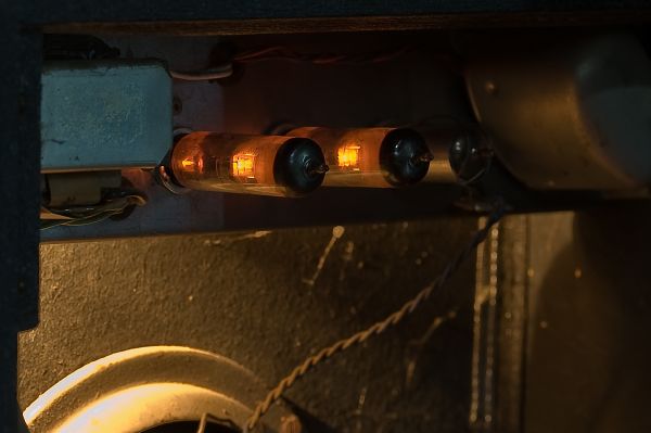
Ramon Clifford is obviously a photographer as well as a guitarist because he has sent in some really artistic shots of his newly aquired ET8 Escort. It would be a shame to prune them right down so I've appended them in fairly large size so you can enjoy his artistry.
He found this for $20 at a garage sale. “The sound is crisp and clean (and loud), it has a low hum when sitting idle, the vibrato is fast at 0 and slow at 10, the tone doesn't change much it only seems to add to the volume.”
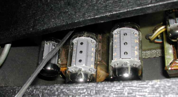
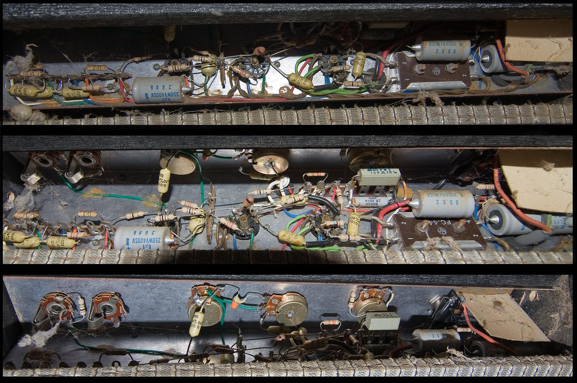
He has also submitted a unique triple-shot of his underchassis that anyone who has to work on one will really appreceate. Click on the key image to download the full size.
Source: Ramon Clifford
|
|

")
