Some effects footswitch builds in detail.
How to build tough, neat, and road-worthy stomp switches.
Contains:
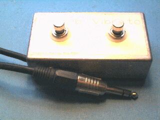
Terry's Fender Deluxe needed a footswitch to control the tremolo and the reverb unit somebody had fitted.
Marking out
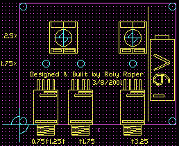
A printout of the artwork below was cut to size and attached with masking tape along the sides to the “bottom” face of the die-cast box, that is the side opposite the lid, as a disposable guide.
An automatic center-punch was used to mark through the artwork where the holes would be. (I use ear muffs when I'm using the auto-pop because the impulse makes my ears ring, a bad sign).
Drilling
Pilot holes about 2mm were then drilled at each point, then each hole was drilled out to its final size. This makes a mess of the artwork.
The cable entry and P-clamp holes were then carefully located and drilled in the sides, pilot holes first.
The artwork was removed and the holes de-burred. The cable entry is a tight fit on the heavy-duty mike cable used, so the hole was over-chamfered on the outside to give the cable an easier time. This hole is also situated as close to the floor as possible for the same reason.
A new artwork was printed, cut out, carefully aligned with the holes, and laminated in place using a pre-cut exact width but over-length strip of schoolbook covering film available from newsagents. The film was continued down the sides and into the lid seam for a neat finish.
A trick with the film is to get it wider than the label so it sticks at the sides, but to stop before the curved box edge, in this case 4.2 inches wide.
Construction
The film was cut clear of the switch holes with an art knife and the switches mounted.
Switch mounting
Like many switches and pots these come with some mounting hardware; a circular knurled dress nut, an inside-star lock washer, and a hex nut.
What Not to Do - 1.
Throw the dress nut and washer away and grinch the hex nut down with a big shifter.
What Not to Do - 2.
Carefully adjust the depth using the hex nut as a backstop, then put the washer on top under the dress nut and grinch down with vycegrips, also rightly called “maulls”. 'Cause they always slip and make a mess of the dress nut. If you don't have vycegrips ordinary pliers will make just as big a mess.
What the professionals do.
Run the hex nut down to the switch. Put the lock washer on. Poke it through the hole. Topside put on the legend plate, escutchon, or dress washer if required (in this case there is a boofy white plastic dress washer to go topside). Run the dress nut on so all its thread just fully engages the shaft and presents a good look. Using a small screwdriver, inside, rotate the hex nut forward until it starts to grip. This nut can then be worked down into the lockwasher using long-nosed pliers (inside!, where slips won't show). A few oblique blows using a drift snugs it in place.
The wiring depends on your needs but if your effect switching is on a TRS (Tip-Ring-Sleeve) connector or similar this wiring should work.
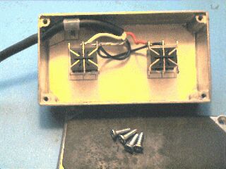
The single plated nut, screw and lockwasher hold the cable P-clamp and also a crimp lug for grounding the case (hidden under the P-clamp, that's where the other black wire goes, not into the cable).
A slab of tractor innertube was cut to fit the lid and glued in place with contact glue. I cut out a suitable pad using tin-snips, wiped the lid with metho and gave the rubber a wire brushing to clean and roughen.
Follow your glue instructions, but typically “contact” glues should be applied in a thin even coating to both surfaces, paying particular attention to the corners and edges, and allowed to set just tack-free. Then the two parts are brought together “in careful alignment” as they say because they generally ain't coming apart again, and you can forget sliding it into place.
Parts
- Aluminium die-case box 111 x 60 x 30, Jaycar HB-5062
- Footswitch, Jaycar SP-0764 or WES Components SWP328
- Mike cable 2 core screened, Jaycar WB-1530
- Neutrik® 1/4-inch stereo phono plug, WES Components NP3C
- P-hoop, screw, nut, lockwasher
Supplers
It doesn't have to be complex to be useful. And they don't come much simpler than this guitarist's effects chain selector.
Peter has been collecting stomp boxes since he broke his first guitar string so he now has a tote box with a very refined collection. Stomp boxes that is, not broken strings.
One day he mentioned the idea of setting them up in two chains. For various performance and song material reasons he thought they would be easier to control that way.
All he needed was a switch to select which chain.
After a few more beers it had resolved into yet another stomp box with some sort of indication to show which chain was active.
The indication was required because the switches have no indication of their state and professional musicians like to launch into a song from silence rather than stealing their own thunder with equipment and setting testing.
These should have been worked out at practice and noted on a cheat sheet if you have a bad memory like me.
At the time I mentioned a mute switch for silent tuning up but Peter didn't think he'd need that.
I ordered a suitably tough and chunky die-cast aluminium case since it was going to get regularly jumped on. Covering the bases I also ordered the next case size up and an extra footswitch for stock.
The standard footswitch part is one size fits all. Mains rated DPDT (Double Pole Double Throw) push-on/push-off with a solid metal plunger and a solid stop. If you hit it with a sledgehammer you'd stomp it through the panel before you over-actuated it, it's that solid - seriously industrial.
Mains rated switches often have silver-cadmium-oxide Silcadox contacts to resist arcing which have a breakover potential of tens of volts and won't carry small signals reliably, but no problems like that have come up with these switches so I suspect they are plain hard silver contacts. Gold-flashed contacts are best for low-level signals but hard to obtain over the counter.
Anyway, just as I was literally about to apply drill to metal, Peter dropped in and said that he had been thinking about the mute switch idea, and that if it wasn't too late could I put that in as well?
I put the drill down and went back to EasyTrax to work out the physicals for the two switch version.
Circuit
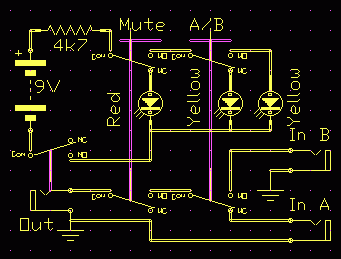
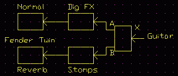
Below, the A/B footswitch selects the signal from the A or B effects chain and routes it towards the amplifier.
The mute switch interrupts this signal and shorts the output (not shown).
Above, the other poles of the switches are used to switch three LED's to show the switch status when on-stage.
Peter says the LED's are invaluable when you inevitably select the wrong chain or are about to play still muted, allowing pre-recovery from the error.
Musicians secret: research reported in New Scientist showed that experienced music sight-readers made as many errors as less experienced readers, they just became more proficient at covering them up and not stumbling.
Rock 'n rollers say, if you play a bum note, pay it again and everyone will think you're being creative.
Layout
I used high-efficiency LED's in the 5 candella range allowing a very low running current, 2mA in this case.
Depending on the LED's you use, the resistor should be chosen for reasonable brightness at the end point of the battery, say about 4-5 volts.
Battery life should be close to shelf life if the unit is unplugged after use.
In this case holes were cut in the artwork using a wad punch, but the film was left intact over the LED holes, the LED's being poked in from behind and glued in place with clear Silastic™ (silicone rubber) sealant. This makes a good glue and encapsulation that can be dug out of needs be.
Construction
Like most stomp boxes it uses a 9 volt battery, and also like most stomp boxes the power is switched by an isolated contact on the socket.
This is sometimes done using a stereo socket and letting the jack sleeve do the switching.
The only problem with this is the 9 volt pulse it feeds into the amplifier, and while it's unlikely to damage the amp front end, if it's turned up at all you could easily blow a speaker.
Besides, cracks, blurts and other non-musical equipment noises are not a good look on stage.
The battery was wrapped in bubble-wrap which not only holds it well, it also provides some protection against battery leakage.
Operation
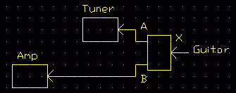
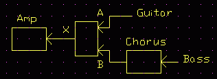
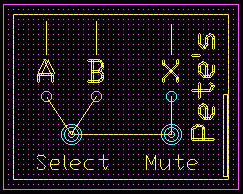
While the circuit is marked with “In's” and “Out”, these are only conceptual. You might prefer “A”, “B” and “X” on the box as I did.
This is how Pete was originally using it with the Hip Pedlars;
This is how he has been using it lately in the Blue Sliders;
This is how Helen used it doubling on guitar and bass (and piano accordion) in the Chinese Fighting Chickens;
Again, unexpectedly useful for something so simple.
Testing
- Put on hob-nailed boots.
- Place the box on the floor next to a speaker stack.
- Climb onto the stack.
- Jump down on the box with both boots as hard as you can.
- Plug it in and make a really loud noise.
(I'll bet you've been dying for someone to say that to you for years ;)
Parts
- Aluminium die-case box 119 x 94 x 34 Jaycar HB-5067
- Footswitch Jaycar SP-0764
- Jack sockets Jaycar PS-0182
- Red 5Cd LED Oatley
- Yellow 5Cd LED's Oatley
- 4k7 resistor
- 9V battery and snap
Supplers