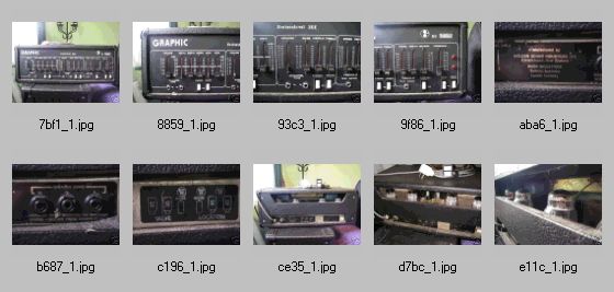
Click on proofsheet to download as zip.
|
http://www.ozvalveamps.org/holden.html | Last update:
2021/05/18
<<<OzValveAmps |
Ian Johnstone, Doug Henderson, WASP Industries, Sydney, established 1967. (says one source)
Built by Holden, NZ. (says another)
Built by Ron Holden in NZ and imported into Australia by Wasp who apparently sold them badged as Wasp. (yet another)
For the real story from Ian Johnstone himself, see The Good Oil, below.
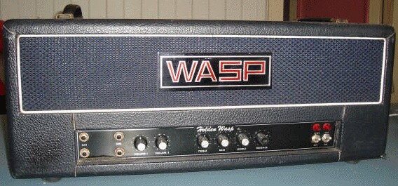
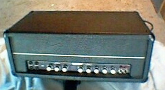
Contains:| History, 200XL Rebuild, Slave 200, 100 Reverb Combo, A Wasp 50 and 100, 4x KT88, Holden 100, 4x KT88 Slave, Holden 50. |
Clarry Schollum of 34AUDIO in NZ wrote (24/9/07):
you have this well documented for the Australian end. Holden in NZ brings up the name of Mike Lewis (I guess after Ron Holden departed our shores) Also did odd things like pedals and reverb units (I have a Holden Phase 3 pedal)
Update: 14/1/08 from Ian Johnstone
Just come across Nick Bertrans email from july 2007 re his Wasp amps.
The one attached was built in the late sixties and was the 4th we assembled in Australia.
Any Wasp with a serial number from 1000 to 1999 had a chassie built in NZ by Holden, and any Wasp with a serial number 2000 and onwards was totally built in Australia.
On Mon, 21 Mar 2005 Andrew McWhirter wrote...
I have an interest in old Holden/Wasps (I have one here!), but I have a slightly different story to their genesis.
Some of this is from an NZ connection who used to frequent our group in the early days and had actually met Mr Holden (who was still in the biz -though making SS PA amps now if I recall).
Anyway, though the first Holden WASPS may well have been imported from NZ, they were certainly manufactured here at some point. The amp I have was bought from the original owner who picked it up from the factory (down around Marrickville in Sydney as I recall) in the mid 70's.
The amps were originally close copies of the NZ designed/build amps. One thing that seems to have people confused is that in NZ, Holden was the company, a WASP was simply one model (like Marshall/JCM800 or Fender/Bassman).
They also made other models in NZ - for example there was a VLB (Vocals/Lead/Bass). But as far as I know in Australia, WASP was the company - or at least, the badge on all the amps, and the guts of the amps were pretty much whatever was lying around at the time. My amp is a 4xEL34.
Another one I know of built shortly after mine for a friend of mine was a 2xKT88 like the one shown (below). The power tranny in my amp is almost certainly a salvage job, with a date code that puts it into the mid 60's.
On the 27th of Jan 2006 I received the following e-mail from Ian Johnstone himself which should set the record straight.
Dear Roly,
I have just come across your site regarding Oz valve amps, and find it very interesting, as it envolves Holden / Wasp amplifiers.
As there seem to be some myths regarding their heritage...
I started Wasp in 1967.
Ron Holden was at the time building Holden amps in NZ that looked like Fender amps (with the controls at the top).
I had Ron redesign the heads to resemble the classic English amps like Marshall and Orange etc. I also had him totally design me a new model that had similar controls to the Marshall 100 lead amp.
Wasp was originally a model name, but when we setup in Australia, we did not want to use Holden, as we had no Auto in our range.
For the first two years or so Holden made the chassis in NZ and we did all the cabinetry in Australia.
After that all amps were built under license in Australasia. I went through three models of valves in the 15 years I ran Wasp; EL34's, KT 88's and 6550's.
In the mid seventies, Ron Holden sold Holden in NZ, and moved across to Australia. He and I formed another Company called Holden Wasp International, which was mainly involved with importing and distributing components and parts for amplifiers and cabinets.
Kind regards
Ian Johnstone
Sales Manager South Pacific Region
APAC AUDIO PTY LTD
Northmead NSW 2152
Thanks for setting the record straight Ian.
New: 13/11/09
This question from “Spittin Blood” . . .
Re: WASP 200 watt Head info needed
from: Spittin Blood
Hi Lads.
I bought this WASP Bass Head last year, haven't used it with a band yet though as I have read they can blow up easily & there a bit unstable.It's a bit noisy with a bit of Hum going on, but its loud & clean & sounds good with my selection of pedals.
From what I remember not many Power valves can handle these. They must be older KT88's.
Since I'm thinking of taking it out on the road, just wondering if there is anything I should know & look out for concerning these amps?
Produced this answer from Chris . . .
I love mine - balls out thing with a SD1 up it's arse!
I'd have it looked at if you are not keen yourself by Reynolds or Dwayne or someone.
There are a few things to look out for basically because they are old, and don't possess the same build quality as a lot of the gear from the era.
In short, a potential widow maker - YEAH.
Standard “it's an old amp checks” need making.
Big one is the filter caps, especially if it is a made in NZ version like mine (230vac mains) - they are 350v rated, and last I checked mine the top plate voltage was 700dc. I changed mine for some newer higher voltage rated ones as a precaution.
Get the right valve combo - can't remember off hand which way around-think mine uses a 12AY7 to drive a 12AT7 phase inverter, or could be the other way around. AX7's here sound wrong.....
The pair of horizontal mounted, north/south preamp pointed valves on the panel above the controls don't have a lot a space between the chassis and the steel plate these are mounted to. The spacers on mine were brass - got changed to longer plastic ones because of it's improved non-metalalic insulation properties........
The chassis is made from some very week sheet metal that is unusual as you can solder to it it bends very easily from the weight of those boat anchor tranny's(check the insulation on them - they looked bad on mine - ok but re-insulated em after a meggar test), and this lead me to re-enforce it with extra screws and aluminium flat bar. Make sure too the pot panel is continuos with the chassis of the amp - it is held together with a pair of 1/8“ self tappers that don't quite make it.
All of the preamp tubes are PCB mounted on very thin (probably beefy for the time) stuff-look for cracked and lifting tracks as the heat had warped mine-I changed all of the preamp sockets to ceramics as well-the tracks lifted whilst doing this so very easily - big tracks so the repairs are reasonably easy.
All in all they are an unusual amp in the fact they are built like LADA? (horrendous state built soviet vehicle brand?) but sound so great-kinda like good sex that lands you at the VD clinic.
Chris.....
Aussie Guitar Gear Heads forum.
New: 13/11/09
Source: Adam Phillips
New: 14/03/09
Alan Farmer writes from NZ...
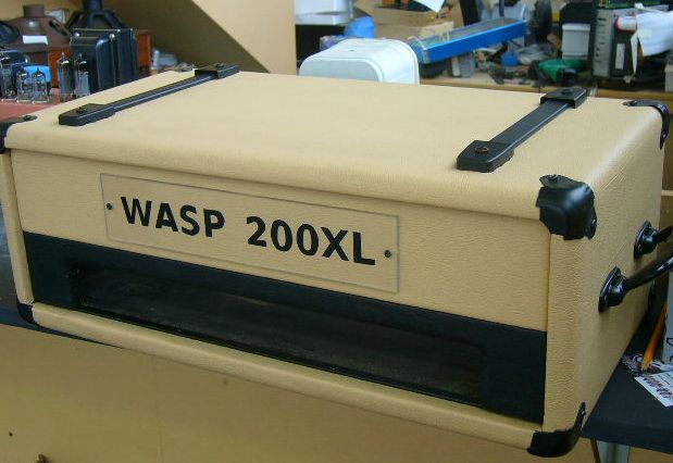
Here are some photos of the amplifier as acquired and during restoration.
The amp had been modded to operate on one preamp valve and also single ECC82 PI/Driver.
The driver PCB was such a mess that I opted to make a new one using etch resist pen.
To get the layout I stripped the old board and photocopied it, marked a new piece of copper clad board with the original hole positions marked through with a scriber and then joined the dots with etch pen, improving the widths and track layout at the same time.
A fresh waterproof marking pen from your local newsagent, such as ParcelMate, makes a very effective and cheap resist pen for hand etched PCB's. -rr
Most components were replaced, some extra filter caps had been stuck on the chassis with silicone. Why escapes me; the original 4x 100uF caps re-formed perfectly!
I cleaned and painted the chassis with black etch followed by very dark grey metallic acrylic. Same with transformer covers, but left the laminations black etch.
All pots new. A master volume had been added so I left that mod in to fill the extra pot hole in the panel.
The cabinet I re-covered with cream beige vinyl and added new black corners and carrying handles.
The only things left to do are add a sheet metal screen in the cabinet (under the chassis) and fit 2 indicator bezels.
Other scratch build projects can be seen on Google “ guitar amplifier repairs howick”
Regards,
Alan Farmer.
A fine job Alan, very well done!
There is a fuzzy line between a repair, whch may be a single fault and only take a few hours of bench time, and restoration, which may require a number of items to be fixed. It doesn't often get much deeper than having to re-create a printed board as Alan has done here.
One thing he doesn't mention is that his chassis has obviously suffered flashover fireworks at some stage in its life. Three elements can be seen here, the brown stain directly above the 220 ohm resistor, dense blackening to the right of the socket, and black whispy soot at the edges.
The brown stain is typical above a chronically heated resistor (remembering that the chassis deck is “up” in normal operation). The dense black splat marks are typical of a flashover and continuing arc with a high power DC power supply. The curly soot traces are more typical of burning plastic insulation ignited by the initial arc (and here patched with tape).
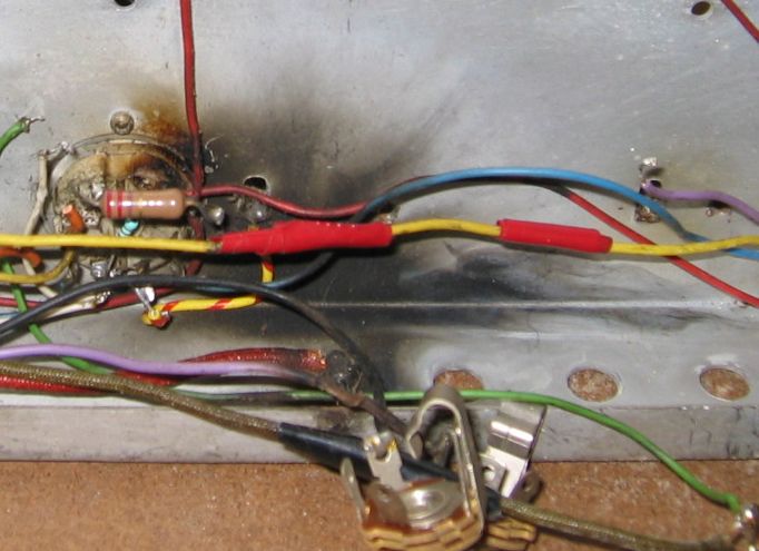
This carbon gunge can be very hard to remove since it has been effectively sintered into the surfaces, but it is vital to remove it from at least the socket because it's conductive. Here Alan has removed the socket for proper cleaning, but I would normally be inclined to replace such a carbonised socket with a new one.
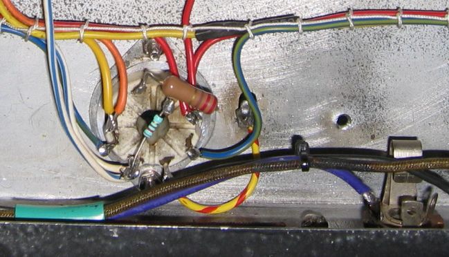
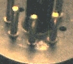
Be warned that cleaning may only be satisfactory with ceramic sockets, and that the more common phenolic (black or brown) types are deeply carbonised and generally not recoverable when inter-pin arcing occurs - as with this valve base:
New: 21/1/08
Simon Morton writes (5/11/07);
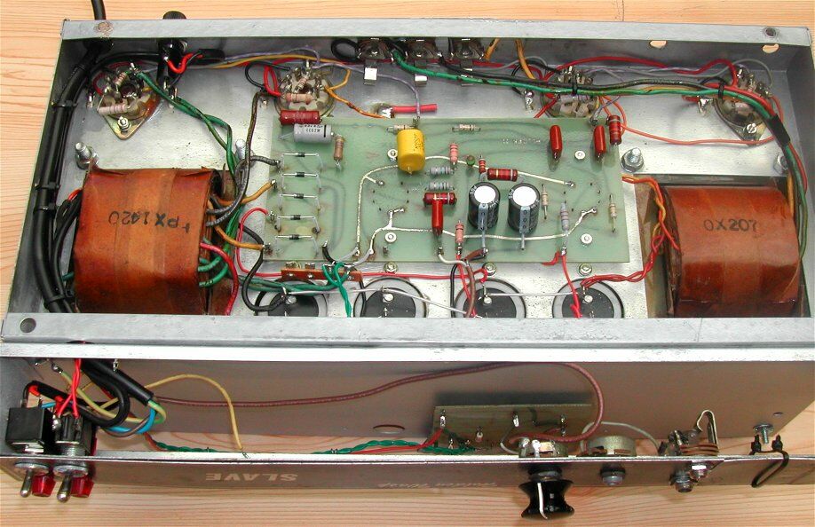
I've recently picked up a Holden WASP 200w 4x6550 SLAVE from the early 70's.(i think?) After doing a bit of poking about from your very website before buying it , I thought it was only fair to share.
I bought it around 3 months ago from a fella interstate. Apparently it had sat in storage for close to 10 years without use. Unfortunately, it was dropped and smashed in transit by TNT - but I did get an insurance payout in the end.
I had to get the chassis straightened, due to the large warp, and replace the broken power tubes. The original tubes (-=smash=-) in the amp (according to the seller, had never been changed) were GE-6550A's. I have since had those replaced with the Svetlana 6550's, and the other tubes shown are Electro Harmonix 12AX7's.
The amp is now working smoothly, and on gig duties - many thanks to my local amp guru.
The amp itself is quiet when running at high volumes, despite people telling me these WASP's were noisy as hell. It does have a slight hum that increases in volume as the overall volume is increased - but this is only very small, barely noticeable.
I have found this amp is sensitive to bad power. A power outlet with a dodgy earth will result in this amp giving a slight buzz off the strings, but most places are good.
There have been a few modifications done to the amp, but not by me. The regular inputs of two - have had two more added to the front. All four are currently connected, although one has a small resistor-damper. There is also another input on the right-rear of the chassis - although this was dis-connected, as the wiring didn't actually connect to anything.
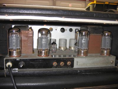
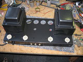
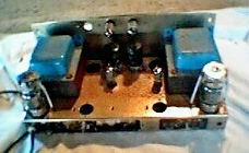
A great restoration - and look at those tranny stacks!
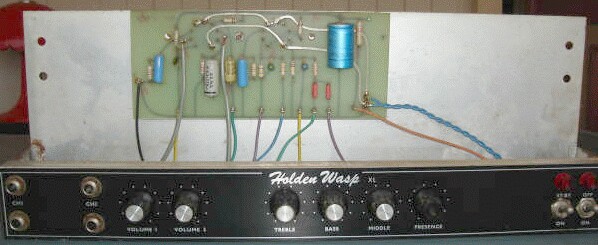
Serial: 2247 which makes it Aussie-built, with transformers Px1622 Ox207.Close-ups of preamp and main amp Printed Circuit Boards.
Looking at the speaker connectors, I had a thought...
ohms=8
	ohms = 8
watts=200
	watts = 200
' P=I^2R, sqrt(I=P/R)
amps=Sqrt(watts/ohms)
	amps = 5
Pkamps=amps*Sqrt(2)
	Pkamps = 7.071067812

ohms=4
	ohms = 4
watts=200
	watts = 200
' P=I^2R, sqrt(I=P/R)
amps=Sqrt(watts/ohms)
	amps = 7.071067812
Pkamps=amps*Sqrt(2)
	Pkamps = 10
...hmmmm 7 or 10 amps. Now, what was the current rating of a standard 6.5mm jack plug and socket again? Would you try and charge your car battery through one? I don't like to see classic amps modified, but in cases like this I think there is a strong argument for retofitting quality XLR's for the output.
New: 20/1/08, from Dean Bennison.
Serial: 1149
Nick Bertram wrote:
I have three Holden Wasps, one 50 and two 100 watt heads all different.
The 50 watt is Holden Wasp XL with two 6GL6's and four 12AX7's. I bought it for $400 back in 1998 and havent looked back. In fact I sold my Marshall 1971 50watt Artist head as it was now never being used.
This is the earliest head out of the three but Im not sure what year of make, maybe early 1970's? It has the heat vent in the roof of the amp which no other Wasps have as far as I know. Serial no. is 1149 made in Five Dock Sydney.
Two channels hi and low, bass, mid, treb and presence on the front. I had a master vol put in to run both channels patched at max, sounds awesome! Very Marshall JTM but with more grunt and somehow Australian sounding?
4, 8 and 16 Ohm outs and no other effects, just pure power. This has to be the earliest Wasp front and grillcloth as well, however the chassis, box, control panel and design are almost identical to my 100 watt. Channel 2 is a push/pull pot for extra treble which I have never seen on any other Wasp either.
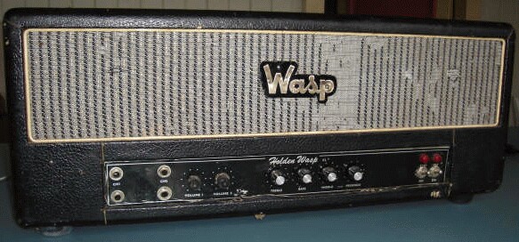
Second is the Holden Wasp XL 100 watt head with two KT88's and four 12AX7's.
This amp seems to be the most common of the Wasp heads and I'm guessing made mid 70's as I have seen Radio Birdman and the Saints use them early on in their careers.
This amp has tons more headroom than the 50 but is no quite as good sounding tonewise, but still great! Bought it for $450 from Cash Converters last June (got em down from $900) and had a master vol put in as well to bridge the channels.
Source: Nick Bertram
15/12/04
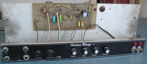
Source: Allan Roper wrote:
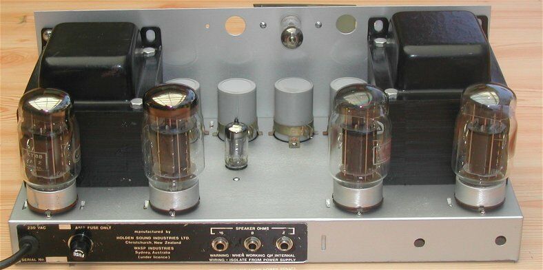
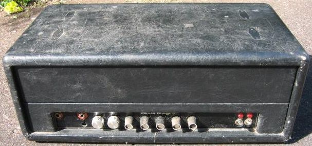
I also have a KT88 powered Holden Wasp 100.
I'm not generally given to gushing, but this is one very neat looking head.
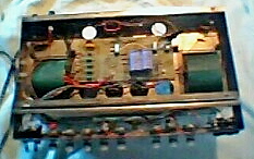
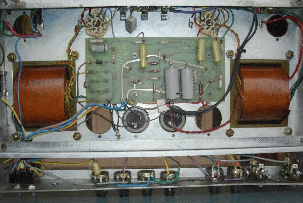
There is a PCB that carries the power supply and output stage components. Unlike the purists I don't have a problem with a properly designed printed circuit instead of turrets or tagstrip, only in modern valve designs where you have to demolish the equipment to get at the copper side. These boards look more accessable (and try getting to the underside of a Fender turret board ;).
The two empty holes at the back will be for a quad arrangement, and from the size of those thumping trannies I'd believe it makes 100 watts in this confguration. Tranny caps suggest quality components. Floating nuts secure the chassis downward through the case floor.
New: 2/7/06
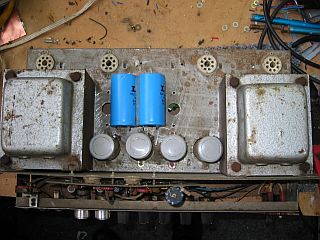
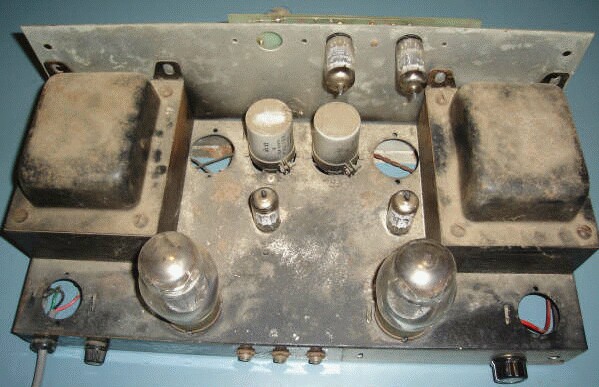
Undressed above chassis front view
Undressed above chassis rear view
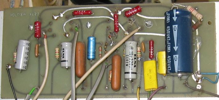
Source: Neil Rote, Grouse GuitarsThere seems to be some sort of pre-amperage on a PCB mounted sideways on an upward extension of the front panel, and the low-level stages seem to be clustered together front-centre, cringing away from the trannies like they should be. But no valve cans.
The KT88's are the old style fat ones where the glass is a more comfortable distance from the anode. The valve-hold downs are another quality item (but beware old tiedowns that had asbestos string wrapped around the ring). The back panel looks chokka with connectors.
The whole impression is of a quality item, from the case to the massive ironmongery. The only thing that worries me is having the KT88's so near the chassis corners and hard trannies, but with such big bottles and big trannies the options are a bit limited.
The 200 watt version with four KT88's, if Ron Holden ever built one, would have been formidable.
(see also Slave)Andrew McWhirter continued...
My amp also has a different pre-amp to others I've seen, with only two inputs (not 4) and the “channels” are not separate - CH1 cascades into CH2, much like a Marshall of the day (JCM800?).
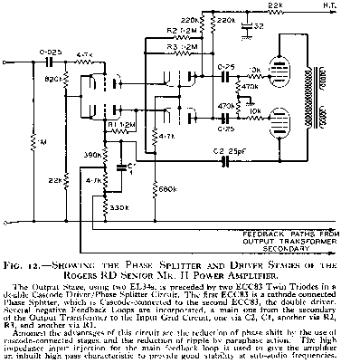
The other oddity with all Holdens (including oz WASPS) is that the phase splitter uses one valve (12AT7 from memory) and then each phase drives half a 12AU7 which in turn drives the output stage. I was told this was not uncommon in hi-fi amps at one time though not guitar amps.
e.g. from High Fidelity Sound Reproduction, Newnes, 1958
I've owned mine for over 20 years and can say they're pretty reliable, but the circuit boards are not wonderful.
The front preamp board is particularly badly done, screwed to the chassis with the valve bases wedged between the PCB and the metal. Over the years that causes the fibreglass board to cave in and leads to stresses/cracks on that board.
The simple fix is to put some spacers on the screws to correctly space the board away from the chassis. By the way, even in mine the boards are marked HOLDEN, so I guess whatever arrangement the Oz guys had with the NZ company they either got the boards from NZ or at least used the NZ overlay.

Circuit of 4x EL34/6CA7 100W amp, 22kb .gif.
Note that this one has a weird power supply (doubler), and I'm pretty sure that most of them weren't like this. The printed schematics certainly aren't.
[New: 14/1/08] Luke Perry-Gore points out the fusing in the mains infeed. The 3 amp fuse shown in the active lead would seem about right, but there should be no fuse in the neutral line (and 5 amp would be too high to protect anyway)
[New: 26/12/10 It has been drawn to my attention that the output valve supressor grids are shown as being directly driven by the Phase Inverter. These elements are normally connected back to the cathode and I can't recall ever having seen anything like this before. There may be a good, if obscure, reason, but it may also be an error, if not in the circuit tracing then in the original amp construction (it happens).
Close-up of preamp printed circuit board, also thanks to Luke.
As for Wasp history, I found something on the web that might be of interest here! From http://www.juliusmedia.com/.
Voltage doubler HT supplies seemed to become more common later in the valve guitar amp era. These were generally associated with EL34/6CA7 output stages, so much so that when I see EL34's I expect a voltage doubler supply.
A tiny point, either the neon pilot light needs about 470k in series, or use one with an internal resistor, but be sure that it does because those with and without can look very similar.
The values used for the cathode bypass caps are quite small which will tend to make the amp toppy.
Normally the missing coupling cap values would be around 0u1F but in this case might be lower.
The tonestack looks like Fender, so that shouldn't present any problems.
The last preamp stage seems intended as a crunch or overdrive stage.
The power amp is one of the rarer ones that use a post-phase splitter driver stage, a cathode follower in this case. Looking at the power rating of the grid-1 series resistors it seems some grid current was expected, so we may assume this is a Class-AB2 or B2 stage.
Finally, the output valves grid-3 is also driven as grid-1 another Hi-Fi crossover.
(4/2/06)
From Kevin Apps in Queensland:
55kb
124kb
18kb
40kb
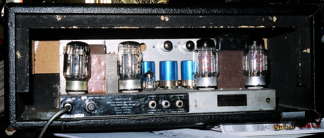
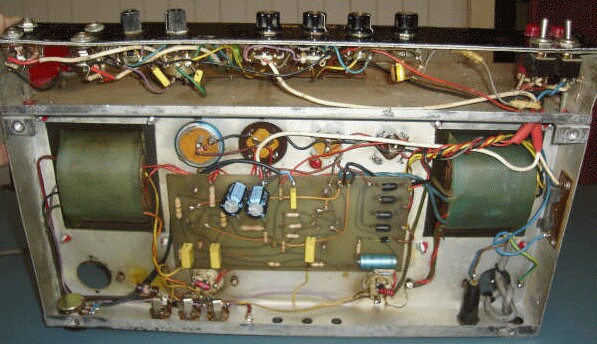
I have what, after looking at your site must be a 200 watt “slave” model. The story goes something like this:-
About 10 years ago this amplifier turned up on my doorstep, it had been found on the side of the road, most likely fallen off the back of a truck!! Although the road did lead to the local tip, so who knows?
The case was smashed as were three of the KT88's, now I am a keen vintage Hi-Fi man and enjoy restoring amps, usually with an output of 15 watts or so. 4 KT88's and over 600 volts HT seemed a bit daunting, however I am now older (and wiser?) and this looks like a great restoration project.
Before starting I traced out the circuit and indeed as you say the phase splitter is followed by two cathode followers feeding the KT88's. The phase splitter circuit did not make sense as the only return to earth for the cathodes was via an 82k resistor and the secondary of the output transformer, although I noticed there was a solder tag which had no connection on it. One half of a 12AX7 is used as a preamp stage the amplifier requiring 5 to 100v rms input.
I was pleased to find your circuit of the 4 x EL34 model [above] and see that it had a “brite” control so I'm guessing mine used the same circuit board but as it is only a slave perhaps there was just a fixed resistor soldered between this tag and earth? [yes]
The only other major difference is that this model used a center tapped HT winding and bridge rectifier, the center tap connecting to a half HT point and the KT88 screens. (I have redrawn the circuit putting the alterations in blue) also the 6.3V winding is center tapped and the KT88 heaters are in series (so it will only work when all four are installed?) [???]
The restoration is not yet complete but will be soon, I will then be making a case.
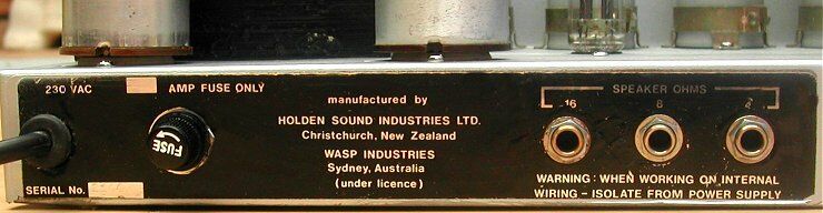
Here are all the details I can see on this unit:-
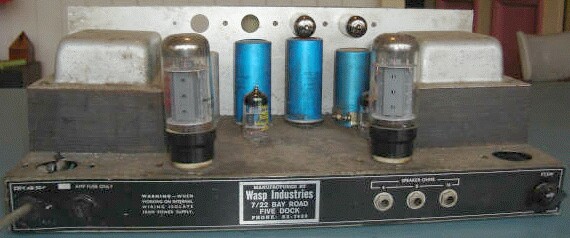
Manufactured by
Holden Sound Industries Ltd.
Christchurch, New Zealand
WASP INDUSTRIES
Sydney, Australia
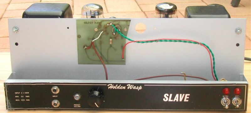
Under licenceSlave Circuit - note the position of the standby switch which removes screen voltage from the output valves, but leaves the anodes live. (see also Standby Switching)
As we can see, Kevin has done a wonderful job of restoring this chassis to “as-new” condition.
On December 15, 2004 my Kiwi namesake, Allan Roper wrote:
I have a Holden 50 watt EL34 head amp. It gets used all the time and is better than a Marshall in my opinion.
(see also Holden 100, above)
Source: ?
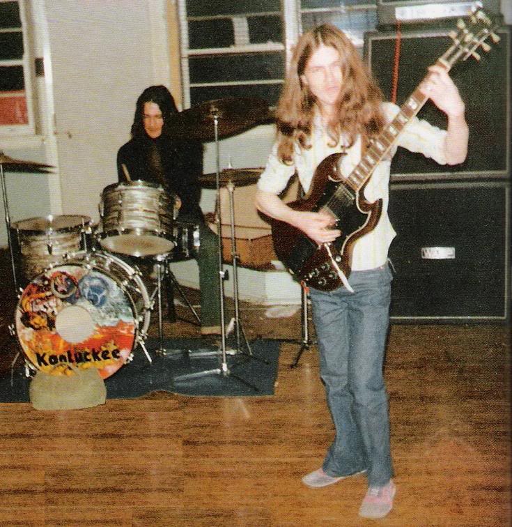
Angus and Wasp
|
|