When restoring a vintage valve guitar amplifier my first move is to clean up the mains wiring to a modern no-exposure standard.
Check the mains lead and plug at this time and replace if required. Rubber insulated “cabtyre” mains lead must go.
Typically the mains active was taken directly to the (uninsulated) back post of a panel mounted 3AG fuse holder (or the smaller M205 in British imports).
From the fuse the active then runs to a single pole mains switch, then to various exposed tag strips for the power and bias transformers. Frantic fiddling with fuses in poor light is all too common at gigs and I don't like the idea of the mains active lurking potentially externally accessable at the bottom of the fuseholder. The old trick of repairing a fuse with foil could be fatal.
Given that the switch is mounted inside a securely earthed chassis, I prefer to take the mains active directly to the mains switch, then to the fuse.
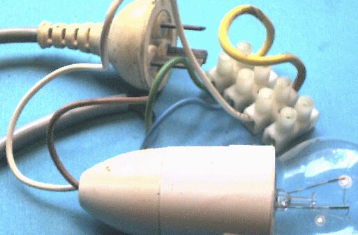
The ideal guitar amp power lead has a correctly wired and clamped (and officially frowned on) cascade or piggyback side entry mains plug.
Now that multi-way plugboards are cheaply available the attachment of musicians to cascade-type mains plugs isn't as vital as it once was (most double adaptors are hopelessly unreliable on stage), but they are still very handy and “authentic”.
The lead should be at least 3 to 4 metres long and of the heaviest duty 3-core mains cable that will fit the plug clamp since it will be walked on a lot.
The cable must be protected where it passes through the chassis, securely clamped inside, then terminated in a four way screw block.
A modern jam-through plastic cable clamp can be used if the available hole is the right size, but insert it backwards, that is from the inside, for better results. If not, use a P-hoop and bolt
I generally replace the mains tag strip connections with a four-terminal length of plastic enclosed screw block type connector.
- 1 is mains lead active (red or brown), to the power switch, then to the back pole of the fuseholder (also insulated with heatshrink), then back to;
- 2 switched active to the transformer(s) and mains pilot light if fitted;
- 3 is the neutral return to the mains lead (black or blue), and;
- 4 is the all-important earth (green or green+yellow stripe) which must be securely connected to the chassis.
If the transformer leads won't make the terminal block, extend them using flying joints insulated with thick heatshrink tubing.
A good mains earth is vital because the user is in contact with the equipment chassis via a guitar most of the time the amp is operating.
This block is also a handy place to add supression caps if desired across the mains switch, and/or the incoming mains. Naturally these should be mains rated.
Once in a while you may find a low value power resistor (10-100 ohm/5 watt) between the ground and the chassis.
This is called a ground lift resistor and like the ground switch is intended to reduce the effect of earth loops. Like opening the safety earth altogether, it works, but is not a good idea.
The right place for an earth lift resistor is in the screen of the audio lead connecting the other mains-grounded equipment to the amplifier.
If the pilot light is a neon connected to the HT rather than the mains then it will be badly internally silvered and possibly burned out due to excessive voltage.
For authenticity it's better to repair with a new NE2 neon in the old holder with a more suitable resistor value (about 1k per HT volt, or 1ma).
Some amps had both mains and HT pilot lights. Strauss in particular used tiny coloured gas discharge lights which came in various colours called “lumo-lights” that are still stunningly cool.
Out with the Megger again and high voltage test at the mains plug, then use the low range to confirm very low resistance between earth pin and chassis.
Remember, guitar strings are deliberately bonded all the way back to the amp chassis, so if it goes live, so do you.