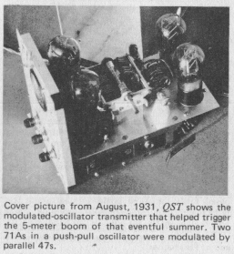
| <<<OzValveAmps |
A trip down memory lane from the beginnings of valves to the 1960's.
Thomas Alva Edison, while fooling around with light globes in 1883, noticed that the inside of the glass tended to blacken after a period of operation. In looking for a cure for this he placed another electrode in the light globe envelope, unwittingingly creating a diode.
He noted at the time that a current flowed from the filament to this extra electrode, which became known as the Edison Effect, but failed to grasp the significance of his observation.
In 1904 John Abrose Fleming applied the effect to radio communication and discovered the thermionic diode detector.
In 1907 Lee De Forest placed a grid between the cathode and anode and created the first amplifer.
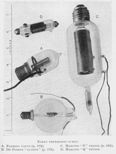
Fleming, De Forest, then Marconi - these were the pioneers, and these are their actual products.
The base on the Fleming valve, “A”, looks for all the world like the standard bayonet fitting still used on Australian light globes.
The “D” style lives on as the festoon-type globes in car dome lights.
The two wires coming in the top appear to be the directly heated cathode, while the side terminal is connected to the anode cylinder (so the two wires exiting right are not joined).
What a wonderfully innocent time when there were so few valve types a one-letter type number would suffice.
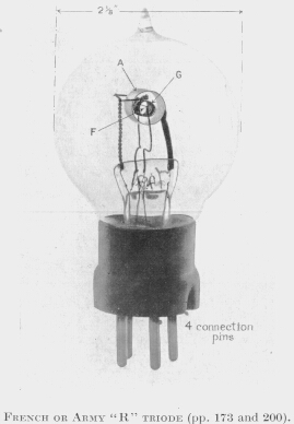
This four pin base became common in two forms. The four pin had one pin spaced away from the others, cruciform-like. Later a fifth pin was added in the middle. Still later this evolved into the base used on 807's with all the pins in a circle, one spaced from the others.
This style of valve, and slightly advanced versions internally, could still be obtained in working order in the 1950's. The pins are expanding in the form of a banana plug.
Some of these even had a large screw terminal on the top for one of the connections.
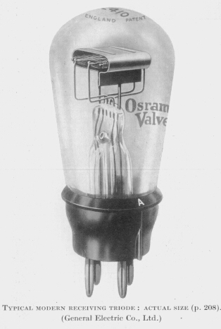
After building a crystal set using the wonder of the age, the germanium diode, I was given a copy of Camm's Beginners Guide to Radio which lifted my horizons to the idea of gain, amplification.
Inspired by the hope of pulling in Radio Luxumborg better, the only pop station in Europe, I started tinkering with valves very like this with low two-digit type numbers.
By the time the series got to 80 it was a rectifier for mantle radios, radio-grams and other items of imposing furnature.
When octal bases came along as the new more flexable standard, the old 80 was reborn as the 5Y3, popular in smaller guitar amps.
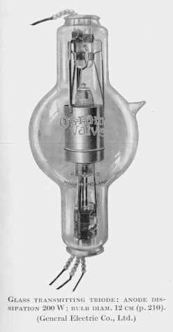
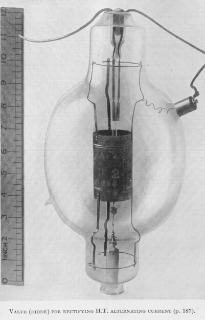
Note the glass beads on the wires as high temperature, high voltage insulation.
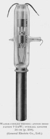
How can a valve be water cooled? In fact pure water is quite a good insulator, steam moreso, so both pure water and steam cooling have been used, particularly around very large transmitter valves.
Even by todays standards, 7.5kW anode dissipation is a hell of a lot in one valve, yet this example dates from 1931.
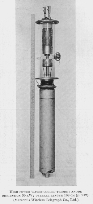
Note the electric field smoothing and flashover rings, top and bottom, This gives some idea of the voltages around a 50kW valve in transmitter service, and how quickly valve technology developed when the spark radio era ended.
The above photos are taken from Wireless by L.B.Turner, Cambridge University Press, 1931.
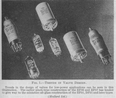
Wartime development brought about new valve construction techniques.
The pre-war style EF37 (left) with it's top cap and metalised paint external screen was already starting to give way to other types by the 1950's, such as the all glass miniatures (centre).
While there was a lot of experience with glass-to-metal seals, the properties of leadout wires were not suitable for pins. The development of alloys that had suitable coefficient of expansion for the seal and stiffness for a pin allowed very compact valve design and much higher frequency operation.
Even before the war Radio Hams were removing the bases of valves and operating them wired-in upside down in attempts to reduce stray capacitance and inductance and allow operation on the ultra-shortwave band (VHF) that was just opening up.
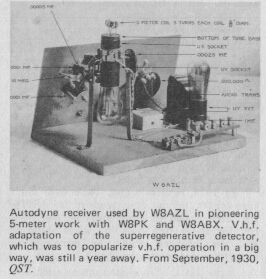
Armstrong had invented FM and valves were needed as oscillators an amplifiers at 100MHz, and all-glass miniatures like these would serve up to 400MHz.
Wartime and the invention of RADAR (RADio Direction And Range) led to a curious development, the metal valve.
The Americans simply “metalised” existing types, normally on standard octal bases. It should be noted that while you may be able to drop them from a bomber without harm, they generally had much lower ratings that their glass versions due to heat dissipation limitations of the package.
The British version of the same idea was something totally different, the Loctal (locking+octal), illustrated above.
While called octal they are in no way compatable. The pins are finer and the metal spiggot has a groove that is gripped by a ring in the base, hence “locking” and it takes a brute wrench to get them out. Like the American version they were thinking very rugged duty, tank and bomber radios and the like.
In both cases the construction is metal over glass, so if you deform the shell, you let the smoke out.
Because of their durability you still find examples of both styles of metal valves, but rarely in service.
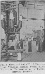
This monster is a mercury arc rectifier to produce DC from poly-phase AC input.
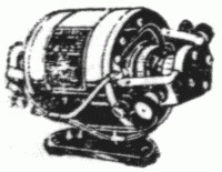
Prior to 1932 High Tension supplies were typically obtained from motor-generator sets, also called rotary converters.
The mercury arc rectifier displaced the rotary converter for a number of reasons;
- 96% efficient against 85%
- voltage control
- high speed protection
- low internal impedance
Note the large ceramic insulator feet, and the fashion victim pointing from a respectful distance! The reason is the entire outside is the cathode at 12,500 volts DC when in operation.
[Sidebar: DC more deadly than AC? If he drew an arc off the AC infeed it would snuff each half cycle, making it easy to break. But if he drew an arc off the DC side it would simply continue. Mind you, at these power levels you're toast either way.]
6-phase AC is fed onto the six anode arms (three in view) from a half-megawatt oil cooled transformer off the infeed to the required transmitter final anode voltage.
Quick sum, 500kW at 12.5kV is 40 amps.
The cathode consists of a pool of mercury in the tank below the anode arm joins. This pool would be around 10 litres weighing around 100-150kg, or more.
Lower power units were made of glass, but the risk of breakage from mercury slosh when handling is real. Hence the steel tank for these big ones, and better conduction cooling.
These actually have control grids and work like a SCR, so control and fast overload shutdown are possible. However to hold them off requires negative bias in the order of hundreds of volts.
Big units are often excited by a flexible striker, magnetically driven from outside, which allows instant-on operation.
Smaller units which can still be found in old Ham gear are heated and require a strict delay warmup before being energised.
It is obviously important to avoid breakage of mercury arc rectifiers, and any such breakage should be treated with due seriousness. Mercury vaporises readily at room temperature and is a subtle, injurious, and potentially fatal toxin.
The above photos are taken from Radio and Television Engineers Reference Book, ed. J.P (Pat) Hawker, Newnes, 3rd ed. 1960.
|
http://www.ozvalveamps.org/oldvalves.html | Last update: 16:46 13/10/05 |