http://www.ozvalveamps.org/repairs/fencer.html | Created: 6/06/11 | Last update:
23:04 26/09/2012 (minor edit/update)
<<< OzValveAmps
|
Electric Fencer Repair
Never underestimate the value of a good electric fence to a band on the “hayshed” circuit.
New: 6/6/11
One of the joys of working with electronics is that you never know what you are going to be presented with next.
I could try to excuse the inclusion of electric fence energisers on the basis that they are second cousins to disco xenon strobe units (which I have also been presented with for repair); but I think the fact that they produce great big fat sparks is enough reason. They bring out the Tesla in me.
Those of you who keep livestock and depend on an electric fence to confine, say, the goats or keep them away from the house vegie patch will already understand that a faulty fence energiser can be a minor disaster in need of urgent attention.

All electric fencing units generate both high (350-700) and extremely high (1000's) voltages. Thus EXTREME CARE MUST BE TAKEN WHEN WORKING ON ANY FENCING ENERGISER (or Xenon strobe).
Mains-powered energisers (and strobes) are particularly dangerious because they employ direct-on mains voltage doubler supplies.
Always disconnect the power, and always discharge the high voltage caps, before doing any work.
|
With suitable care however most fencer faults a very straight forward to repair.
What is a fence energiser?
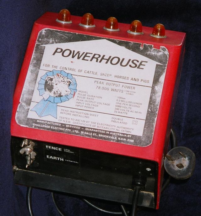
A typical electric fence energiser
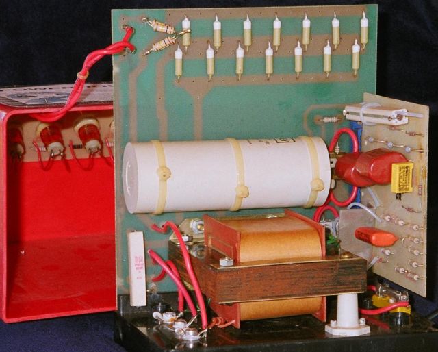
The black “bottom” slides out
The object of an energiser is to send a short pulse of very high voltage down an insulated fence wire or wires. The energy level of these pulses is limited by law to a level where they provide strong stimulus without any danger to health in a typical wet farm environment.
But make no mistake, while these things may not be able to kill you directly they can lay you on your back, and can ignite flammable vapours.
The vast majority of energisers I've seen come in an identical plastic molded case with a cut-off corner, but from brand to internals it is rare to see two the same. The one above has a row of neon indicators, but they often have nothing, or a small solar panel mounted here.
The common variants are battery powered; with solar panel; mains powered; bi-polar output; training mode, and sundry indicators.
The battery powered versions seemed to be much more common (or perhaps fault-prone). Mostly these are wired to an external battery like a an old car battery, but some are fitted with internal sealed lead-acid cells and similar.
How does an energiser work?
Internally fence energisers are similar to Capacitive Discharge Ignition systems in vehicles.
A “dump” capacitor (large white cylinder) is charged to a high voltage between 350 and 700 volts depending on the model, then discharged via a Silicon Controlled Rectifier (SCR) into a step-up transformer, generally similar in operation to a car ignition "coil".
The major elements are a high voltage supply, a dump capacitor, the SCR dump switch, and the EHT transformer as the load. A crude timer is required to space the pulses, and circuitry for solar battery charging may also be included.
“Training mode” were available is a switch that allows rapid pulsing to train livestock new to the fence, and the more power economical “normal” slow pulse mode for stock experienced with electric fences.
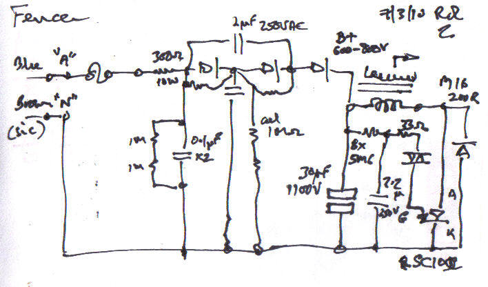
Mains enters left through sundry protection and safety to a direct-on-mains voltage doubler. Take care that your mains supply is the right way around, active on active (red/brown) with respect to local earth (green), not on neutral (black/blue).
This B+ of 600-800 volts is applied to the dump cap 30uF/1100V. This is a special cap designed for high repeat heavy discharge, such as in xenon stobe units. When these fail they generally go very low-capacitance, (mostly) open circuit. If you have a fry up in the power supply, suspect a shorted dump cap.
Pulse timing is provided by the chain of 8x 5M6 ohm resistors, 2.2uF/250V and Diac into the gate of the SCR.
When the SCR finally fires, the charge in the dump cap is dumped into the primary winding of the EHT transformer where it is stepped up to the required kilovolts for the fence. A healthy fencer should throw a fat spark a good 10mm (half-inch).
In battery operated units there is an inverter generally consisting of a simple push-pull, magnetically coupled self-oscillating type. These appear to be electronically very reliable.
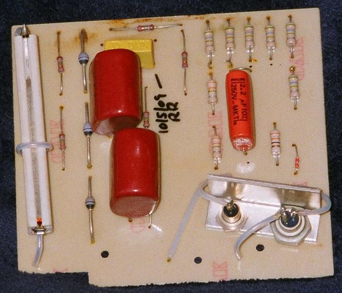
Unsolder the two wires on top for SCR testing
On the left of the sub-board is the mains doubler supply. On the right the dump control and timing, SCR and clamp diode share the small sheatsink.
The brown stain at top is a clue the unit has had water in it at some time, not uncommon.
Typical faults
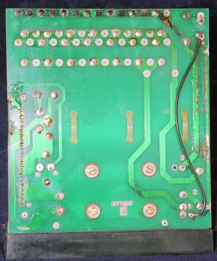
Previously treated for water damage
Dirt is always the first enemy, and never moreso than with gear that is literally “out in the field”, and on-farm electronics is getting evermore commonplace these days.
Where you have batteries you have corrosion and poor connections, so that's an important thing to visit early.
Electric fences are also like a long radio aerial, and being above the gorund and insulated they can pick up quite significant charge from nearby lightning, they don't have to be actually struck to do damage to the energiser.
So the most common fault after corrosion is that the SCR has died. A suitable replacement SCR is the SC10D. The Diac is not critical.
Most of the components in a fencer have a hard life, but as a semiconductor the SCR is doing it particularly hard.
The next most common component to fail is the dump capacitor which is also having a hard life. Jaycar have accassionally carried a suitable unit, but I can only suggest W.E.S Components/Wagners in Sydney if not. (Addendum 26/9/12 - Julian Lavarack reports that Wiltronics have a good range of pulse caps for electric fences Link)
Faultfinding
If there are no obvious signs of fireworks or other damage, and the SCR doesn't seem to be shorted, then you can try as short power test.
With a mains powered unit, clip your multimeter across the dump cap on the 1000VDC+ range, and see if it charges to a few hundred volts.
With a battery powered unit you will need a battery or bench power power supply capable of about an amp (a computer power supply unit is generaly sufficient). The inverter should normally be audiable as a whistle, starting up and rising in pitch as the dump cap charges.
Isolate the device from the power, and use your load lamp or large resistor to discharge the dump cap, lest it discharge through you at some later point.
If you have a unit that charges up and simply won't fire, particularly if you have replaced a faulty SCR, (carefully!) measure the voltage across the Diac.
If it's less than about 30 volts then it may mean the Diac isn't getting to its firing potental, and you may need to look to the timing components. If it's more than about 30 volts it suggests the Diac is stuffed as well and needs replacing.
The following is a suggestion for how a faulty dump cap might be replaced by several flashcaps recovered free from disposable cameras.
Obviously the proper high-stress cap is best, but this may keep the goats out of the vegie garden while it is coming in the post.
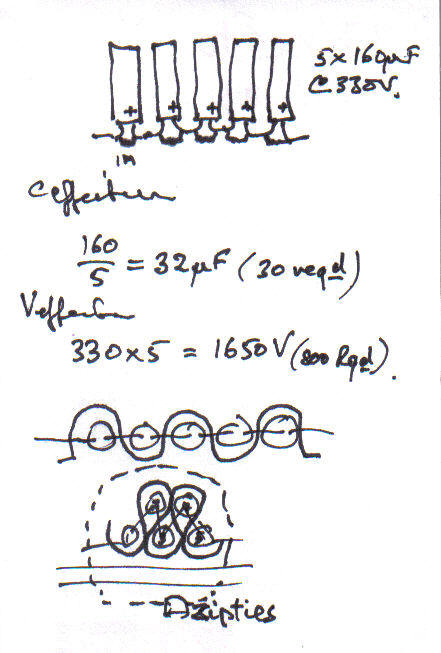
Insulating plastic layer woven between the cans
The fence side
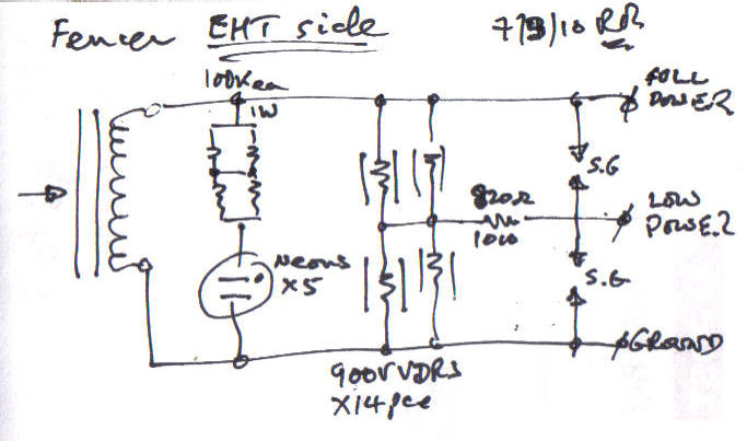
Indicators are variable, but VDR chains seem universal. "S.G." = Spark Gap
The three output terminals on this one were marked “Ground”, “Low Power”, and “Full Power”.
By different names, these three connectors also allow for a three wire fencing system where the centre is grounded and the other two wires driven differentially, each only half of the full voltage between them.
Fault Prevention
Lightning
After the weather the main enemy of electric fencers is lightning. Nearby strokes can induce very high voltages into the insulated fence wires and thus back to the fence energiser (where they typically kill the SCR).
There are two protective measures the user can take, either commercially available, or simply handicrafted in the workshop.
The first are spark gaps.
These consist of an insulating base holding the fence wire and a third terminal holding a wire carefully spaced from the fence wire so that it doesn't quite flashover during a fence pulse. This third terminal is directly and solidly grounded with an earth stake. Lightning induced charge will cause this gap to flash over and shunt the energy directly to ground.
The second are series inductors or “anti-lightning coils”.
These consist of 20 or 30 turns of ordinary fence wire, spaced so as to form a coil about 30cm (1 foot) in diameter and about 1m (3ft) long.
This coil may be hung on a fence strand but must be insulated from it as it carries the high voltage fence pulse.
It must be fitted close to the fence energiser, and before any spark gap lightning arrestors, i.e. the spark gap must be on the fence side of the coil, not the energiser side. As the spark gap arrestors provide an easy alternative path to ground, so this inductance coil represents a major barrier to any lightning going down that path - stick and carrot.
These issues, and others, are covered in more detail in better electric fencing guides, available from your electric fencing supplier.


