http://www.ozvalveamps.org/repairs/transicord.html | Created: 7/7/06 | Last update:
22:56 5/06/11
<<<OzValveAmps
|
Farfisa Transicord
A good news story, even if the valves are at the other end of the lead.
Contains:
New: 5/6/11
Farfisa Mini Compact Service Manual.pdf 1.7Mb
Farfisa Bravo Schematics.pdf
3Mb
Source:
Transicords Revisted
Addendum: 31/12/09
Inspired by Adam.
I am revisiting the Farfisa Transicord because I have been asked to build a power supply unit for one, and after investigation it seems there is a need to clarify the situation and provide some substitute designs.
How hard could it be? Well this apparently simple request resulted in considerable confusion until I found combo-organ.com. While this site only deals with the Transicord in passing, it contains extensive information on servicing the Compact Duo combo organ which is closely related, and provided some valuable missing bits to the puzzle.
History
The capsule history of Farfisa is that it was a merger of several Italian accordion builders, and the Transicord electronic accordion released in 1962 was their first electronic product, the more conventional keyboard line of combo organs following about two years later. For the full Farfisa story see the link above.
One fact sums up the situation; serial numbers were allocated “randomly” according to one employee, so dating any of their products is almost impossible. Overall the Frafisa instrument product line seems to be full of little sidetracks and differences in details.
Farfisa's initial decision to split the electronic accordions and organs into two units, the instrument and companion power supply on the floor, was fateful and has resulted in some instruments being separated from their unique power supply and becoming non-functioning junk.
These are turning up very cheaply on e-Bay and such. My own Transicord Deluxe came with its power supply but “not going” for around $A60, while a non-Deluxe with case but apparently no power supply just sold on “as is, no return” on e-Bay for around $A35.
What we can be sure of is there are at least two major “Transicord” accordion variants, the Transicord and Transicord Deluxe, and they have quite different and incompatable power supply requirements.
If you have, or a considering buying, either model Transicord (or a Compact) without power supply; these are not available over the counter, however anybody with some electronics skills who can build a robust and safe low-voltage power supply, can build a suitable substitute. We will look at this in detail below.
We also know that the plain Transicord accordion and the early Compact Duo combo used much the same electronics internally and the same F/AR power supply, although the relationship between the Deluxe and later Compact combos is unclear.
Like Farfisa organs generally, there are also a number of Transicord variants, mainly using button rows instead of piano keys for the right hand, with markings in several European languages, and different connectors for American and European models, however internally there seem to be only two major variants, the Transicord with one row of voice tabs, and Transicord Deluxe with two.
We might expect that the Deluxe model would follow the plain Transicord, but if that is the case it represents a leap into the past in styling, and a loss of facility with the dropping of the reverb. Which came first? No idea, and given how Frafisa progressed they could have been trying to cover both modern and traditional bases at the same time.
Identification
Transicord
(mod: TD/50 ser: A.92/105)
Uses F/AR power supply. Blue/grey, Hirshtmann 10-pin connector, two supply rails of 9VAC and +24VDC, with reverb, shown below.
|
Transicord Deluxe
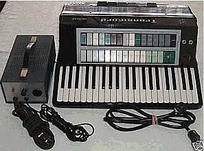
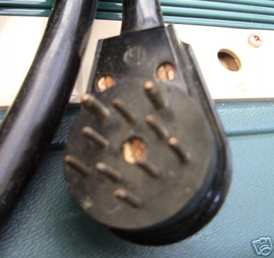
With ATR/3 power supply. Black, octal connector, four supply rails of +21V unreg, +19V reg, +12.8V reg, -15V reg, no reverb.
|
Power supplies
After extensive net searching I found three circuits that claim to be for the “Transicord”. Two of these are from Farfisa and the third is Build your own Farfisa power supply by David Barraclough.
The Barraclough supply
This design is a simple unregulated single supply of around 11 volts. It may get you going, but at best it is an incomplete subsitute for the F/AR supply required by both the Transicord and Compact Duo, as we will see below, and certainly unsuitable as a replacement for the ATR/3 supply for the Transicord Deluxe.
If you understand the limitations of this approach (discussed below) then there is a simpler option of using a wallwart or other suitable supply, and a resistor in series.
The supply must be DC, at least 12 volts, and capable of delivering at least 200-250mA. It doesn't need to be a regulated supply but it must have a suitable resistor between the supply and the instrument in the positive lead.
| Voltage | Resistor (Ω) | Dissipation (W) |
| 12 | 22 | 0.5 |
| 15 | 39 | 0.9 |
| 18 | 56 | 1.4 |
| 22 | 82 | 2.0 |
| 24 | 100 | 2.3 |
(Vout = 9V, Iout = 155mA)
In all cases this resistor is going to get warm to hot, so I suggest using a 5 watt resistor.
If you can find a 9 volt AC unit capable of 1 amp you can also power the expression pedal and “Multi-Tone Booster” function, however any arrangement of plugpaks has to be packaged in some way so that it is roadable and there is no chance of connecting the supplies incorrectly. Naturally this approach provides none of the audio facilities of the F/AR unit.
ATR/3 power supply for Transicord Deluxe
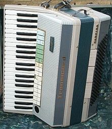
My own Transicord Deluxe model (pictured in the story below) is mostly black, with an octal (8-pin) plug as the instrument connector. The ATR/3 power supply gives +24V unregulated, +19V regulated, +12.8V regulated, and -15V regulated, no reverb line or audio controls.

This is the segmented circuit for the ATR/3 supply,
transformer/rectifier,
positive regulators,
negative regulator,
connector pin assignments,
transistors and diodes,
resistor power code used.
A modern replacement for the ATR/3 could easily be constructed, say in a recovered computer power supply case, using common low voltage transformers and 3-pin regulators. If you already have a dead ATR/3 then repair should be a straightforward matter.
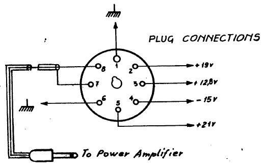
Note that the +21V supply on pin 5 must be fed
via a suitable current limiting resistor.
The overall current required is defined by the fuses used in the two low voltage windings, 1 amp total for the positive supplies, and 50mA for the negative supply.
This is my suggested but so far untried (I don't need one) modernised replacement circuit for the above, with PCB layout suitable to be built in an old computer PSU case. Notes: Some tweeking or scaling of the regulator offset resistors may be required to bring the rails to the required voltages
before you unleash it on the instrument; and the stability caps on the PCB are not shown on the circuit.
All due care but no responsibility; if you build one of these I'd like to hear how it went.
F/AR power supply and reverb
for Transicord and Compact Duo
Circuit of Farfisa F/AR power supply and reverb unit.
This supply has a Hirshtmann ten pin connector with the pins in two pentagons as the instrument connector. The power supply produces +22V unregulated, a floating 9V AC, contains a reverb line with power driver, and has a preamp with controls for volume, treble, bass and reveb (F/AR unit pictured at foot of page). It also features an “arrest” lever to damp the reverb line springs during transport, something all springlines could do with.

Hirshmann no longer makes the MES-100 or MEB-100
but only six connections are actually used.
This F/AR supply can also be easily recreated using commonly available components. In this case however it may be better to omit the reverb springline in favor of Effects Send and Return connectors.
There are two reasons for this change, firstly finding a suitable case for the length of a reverb line, and secondly that modern effects units and pedals are available these days which are much more versatile than just a springline.
The circuit of the F/AR supply alone still left a couple of questions unanswered. The DC output is fed via a resistor network, thus the actual terminal voltage depends on the current drawn, so what should we expect here? The second question is what the 9 volts AC is used for in the instrument.
An examination of the Compact Duo circuit provided a simple answer to the first; there is a 9 volt Zener diode inside the instrument directly across the DC input. Normally this will act in conjunction with the resistors in the floor unit as a regulator, holding the supply rail down to 9 volts.
Its most likely failure mode is to go short-circuit which will protect the instrument circuitry (at the slight risk of damage to the power supply). Since it is also a diode it provides inherent protection against accidental reverse polarity.
There are a couple of implications in this, firstly that any external supply must also include a resistor to limit the current through this zener. You could get away with a DC “wall wart” of sufficient voltage and current rating, provided it has a suitable current limiting resistor in series.
The second implication is that a shorted zener must be expected in an old instrument that has lost its correct power supply and may have been experimented on.
From the point of view of buying a dead Farfisa the inclusion of this diode makes the electronics harder to kill, and “a pig in a poke” a somewhat better bet.
The 9 volt AC was a bit more of a puzzle and turned out to have some unexpected twists. One commentary dismissed this supply as only being for the expression pedal, and indeed it is rectified within the instrument to light the lamp used with the LDR in the expression pedal.
But it turns out to have a much more interesting use in what Farfisa decided to call the “Multi-Tone Booster”.
The reason the power for the expression pedal opto lamp is rectified and smoothed is because the light from an AC powered lamp pulsates at 100Hz (120Hz), lighting brightly for each half-cycle of the 50Hz (60Hz) mains.
The Cadmium-Sulfide (CdS) Light Dependant Resistor (LDR) cells used are slow, but still have considerable small signal frequency response and would respond to this light pulsation and inject bad mains hum into the controlled circuit. So this light is powered by smoothed DC.
But when we look at the “Multi-Tone Booster” module we see that there are two lamps and LDR's, and that the lamps are connected directly to the 9VAC. So this pair of LDR's is being deliberately subjected to a rapid flutter.
The surrounding circuit suggests that the “Multi-Tone Booster” is a frequency selective network, something like a tone control, being wobbled at 100Hz. Commentry around the “Multi-Tone Booster” tab stop is that it produces a raspy edge similar to the Vox Continental, Farfisa's main rival in the combo market, and that would seem consistant with how it seems to work.
The implication here is that without some sort of power on the 9VAC circuit the expression pedal won't work, and without 9VAC the “Multi-Tone Booster” tab stop won't work either. In this respect the Barraclough supply falls short.
Current requirements
The current requirement for the 9VAC line is roughly 300mA for the expression pedal and about 400mA for the two parallel 12V 3W lamps in the “Multi-Tone Booster” module, say 9VAC at 1 amp for both with some reserve capacity. For the instrument alone half an amp capacity should be sufficient.
The Farfisa F/AR circuit shows +24 volts at the output of the rectifier, and two power resistors of 75 and 22 ohms in series with the instrument feed (i.e. in series with the 9 volt instrument zener diode). The output current is found from Ohms Law as the voltage drop, over the total resistance;
I = E / R = (24-9) / (75+22) = 155mA
Note: two standard 150 ohm 5 watt resistors in parallel make a (non-existant) 75 ohm 10 watt resistor. 22 ohms 5 watt is a standard value.
F/AR Audio path
Apart from the power supplies the F/AR also contained some audio circuitry, a preamp to lift the incoming instrument 60mV pk level to 300mV (gain ~x6) to be sent “dry” to the output amp, and to the reverb springline driver. The springline is followed by a recovery amp which supplies the “wet” signal to the output amp for mixing, which also has a gain of about x6 for a signal level of 2 volts into the following passive tone and output volume controls.
All of the transistors used are PNP germanium, the small signal being OC71's, and the reverb driver and pre-drive AC128 and AC153.
If your F/AR has failed then, with two exceptions, it is a straight forward practical matter to repair it. The two exceptions are the actual transistors, and the springline.
Springlines break at the end suspensions, and if you are very lucky and have watchmaking skills you may be able to repair it. Otherwise you need to find a replacement, or mod it with FX Send and Return sockets.
Germanium transistors of any sort are pretty much unobtainium these days and if you can't scrounge substitutes from an old transistor radio then you are up for fitting silicon (e.g. BC559) and rebiassing the stage.
If you are building a replacement F/AR then it is better to forget the original circuit, but retaining the passive output controls, and use a modern dual op-amp (e.g. LM833) for the pre-amp functions. Instead of a fragile and bulky springline you fit an Fx loop and take advantage of the many units that will give you a selection of reverbs, and much, much more.
The Compact actually uses several LDR opto-couplers, one of which is driven by a neon. A Neon? Sure enough, one rail on the circuit is marked “+125VDC” and comes from a small inverter inside the instrument. It won't kill you, but it might come as a mighty surprise.
Footnote: apparently Farfisa built some of their amplifiers with a socket to match the Transicord and Compact organs, allowing the amp to supply the functions of the F/AR units.
New: 27/6/09
Circuit 1: Master oscillator and divider chain arrangements, note and voltage tables.
Circuit 2: Keying, percussion, and preamps
Source: Peter Hutchison
Farfisa Transicord - Yo!
Originally to ANZAmps Yahoo group, Mar 05.
A while back I was wandering around Melbourne CBD when I stumbled on Lewis's Music which I had long forgotten. He's collected a few oddities, one of them being a dusty Farfisa Transicord Deluxe hanging on the wall.
Farfisa were(?) an Italian electronic organ manufacturer, particularly of “pop” organs, and the Transicord series repackaged an electronic organ design into a piano accordion case - no reeds. I hadn't seen one in decades so you can imagine my surprise at the sign that said “not going - $70”.
I asked him what the symptoms were and he told me it was totally silent even after a couple of bods had worked on it. He thought it was a dead duck and somebody might want it for parts.
I'm not a gambler but a quick haggle and I was the new owner of a dead piano accordion I can't play. From the look on his face it must have been cluttering up his shop for years but he managed not to treat me like the idiot I obviously was.
I located Carlos Molina in Brazil who is a tech and musician with a library of Farfisa manuals, but language difficulties proved too much, so I was forced to proceed blind. No matter 'cause I've serviced lots of keyboards of this vintage and still fancied my chances.
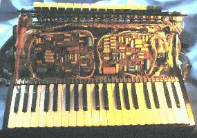
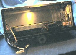
I'll admit that the reconstruction into compact accordion format had me groping for a while. Inside the bellows are the master oscillators and divider chains, all discreet transistors. Above the keyboard are the stops (voice selectors) which swing up to show the tone forming circuits underneath.
The bellows operates a neat LDR device which uses two disks of light polarising material, one fixed the other rotating, to vary the intensity and provide expression and wah-wha(!) control.
The power supply is in a metal box that sits on the floor and connects with an umbilus with an octal connector at each end, producing 18V unreg, 12V reg and -18V reg.
The lack of oscillators was quickly traced to no power on the boards and a broken wire at the headphone socket. This seemed to be related to the vibrato (sic) signal which must also provide some bias for the oscillators to run (not uncommon). Now I had a few very high/supersonic pitched notes and not much else.
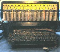
Above, keyboard contact field,
mid/behind, divider chains,
bottom front, 12 master osc's, tuning pots.
I had already guessed that the minus supply was used by the key shaping circuits, and guessed that it was also used to bias the flip-flop divider chain. So when I couldn't find any -ve voltage on the divider board I went looking for another broken wire, and found it. Now we were seriously in business with the whole keyboard and bass buttons coming alive.
Naturally somebody had cranked all the tuning pots during their futile fiddling and it sounded worse than a gamalan so all the osc's were reset on frequency using the bench counter.
The bass side had me confused for a while but it turns out that the bass buttons do not preceed in pitch order, something to do with being able to play in a given key without having to move the left hand too far. So what I initially thought was faulty is in fact correct. Each button row produces basic notes, then major, minor, 7th, and diminished chords.
Bottom, bass button contacts,
right, bellows expression control,
(osc/divider assembly fits in cavity).
After years of sitting in the city miasma of exhaust gasses the contacts are a bit corroded and scratchy but a good clean and a playing flog has cleared almost all the crackles.
And so it was that filled with trepidation I took it around to Helen and Pete's for Helen to try out. I remembered Farfisa's as being pretty cheezy and doodling on the bench didn't sound that impressive. How would they react?
When Helen got a hold of it, it was a totally different story. Forget accordion - this thing only looks like one but is actually a full-on organ that can range from pop to serious church sounds, passing through some Voodoo Chil' Hendrix wah-wah along the way and totally cracking us up.
The bass is huge, fat and smooth (16-foot Diapason), the voicing modeled on a real pipe organ with stops marked in feet like “8 Flute” and “2 2/3 Nazard” (if I recall correctly 2 and 2/3 feet is a Fifth pitch interval).
After a while Helen commented that it was a strain pulling the bellows out for expression, so I removed the major return spring for a much lighter bellows action (a normal accordion doesn't have a return spring, and a much longer bellows action).
So now it's on permanent loan to Helen and they are exploring it's musical possibilities in their band, which should be very interesting.
One thing that struck me was how Farfisa managed to get an effect that sounds very like reverb using only voicing circuits (attack and decay), without a delay or reverb line.
So what are the messages from this story?
* Something that is totally dead is often a better proposition than something with a “minor” fault.
* Any kind of fault can demolish the price of an otherwise useful bit of gear and present a golden opportunity to repairers.
* Totally daunting to look at, the problem was actually very mundane - a couple of broken wires, nothing really electronic at all, yet it seems to have defeated at least two other repairers.
* Experience, expertese and circuits can get you there fast, but the steady application of commonsense and careful observation can still get you there eventually.
Circuit of Farfisa F/AR power supply and reverb unit to suit Transicord and Compact Duo models. This is unregulated unlike the smaller supplies, but includes a preamp, reverb unit, and shows connector wiring for both European and American connector versions.

Version with American connector. Note reverb line arrest lever.
Some Organ Basics
OMG!
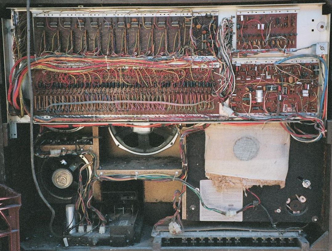
This nameless one was already a lost cause, but in its day it cost over $1000, and had a built in cassette tape unit, side-man beat box, lots of brightly coloured stops including one-finger chord left hand.
From the bottom clockwise; the power supply, main amp and expression pedal chassis; multi-way speaker system.
The board across the top-left has 12 IC's so will contain the master oscillator and octave dividers for each of the basic notes; the board under will contain the attack/decay circuits for percussion and other trnasient voicing.
The small board top-right is most likely the electronic drum kit consisting of a longish shift resigister or counter+decoder, together with damped oscillators, gated noise and voicing circuits for the purcussive effects.
The most chaotic board, mid-right, is normally the voicing board that defines the available tab stop voices. I guess the chip in the middle is a solid-state chorus generator.
Lower-right is a two-speed rotating loudspeaker (behind padding).
Bottom right is the rear of the bass pedal clavier.
A simple organ
These are original circuit traces of an old AceTone I once had; 5 octave, 4 voice and vibrato.
The signal flow starts at top-left with the master oscillators.
Since tuning is a primary reason to go inside one of these boxes without a tourist guide, the main interest is normally in the master oscillators. Because there are 12 notes in an octave we look for the board that seems to have 12 of everything.
This is the Master Oscillator and Octave Divider board (or boards). Some for of tuning adjustment, generally by screwdriver, will be available. This may be pre-set pots as in the Transcord, or tiny copper screws as in the AceTone.
All the available notes generally make their way out to the keyboard buss bars and multi-pole switching contacts.
The keyboard switch matrix also has a number of output busses so that the selected signals can be sent to the required voicing circuits, bottom-right, selected by tab stop. (the high-pass voice drivers are shown at below)
The voicing circuits are shown below. Switching is in shunt, that is the tab stop contact is shorted when the voice isn't required.