The nice folks at Everyday Practical Electronics (ex-Practical Electronics) in the UK have sent me a nice little Atlas LCR bridge for saying nice things about them. Payola! Cash for Comments!
Even small LCR bridges are normally big to accomodate all the knobs and range switches and so on. This thing uses PIC magic to do the same job automagically with only two buttons, and small enough to slip into your pocket or toolkit. I am a bit dubious about black boxes like these because they can sometimes return a really berko result with great authority.
I've been trying this one on everything in sight and it hasn't been tricked so far, even told me the cat was 8.2 Henries and 890k which sounds about right. The only con is that it uses AAA batteries rather than AA's.
So while pondering current drive for reverb lines I decided to use this new toy to check with reality (well, its opinion, anyway).
Pulling out the reverb line stash I found the following:
- A large tank marked 460 with broken taut-wire suspensions which may be from an old Fender Twin. This also has a 0.002uF disk ceramic fitted internally across the output which will parallel resonate the sensor at 6KHz.
430 x 110mm overall. - The a Pioneer EAV-201 line I have had for years. Ex-equipment, possibly from a console organ.
300 x 60mm. - A new Belton SN2AA1A1A from Korea via Jaycar. This is the one used in the Silicon Chip “Spring Reverberation Module” article, Jan 2000, and sold as a kit by the normal suspects (Jaycar KC5282). Now all discontinued due to unavailability of these lines (or possible saturation of the reverb kit market). The delay is 22 and 27mS with a decay up to 2.5 Secs.
260 x 60mm - A mini oddity, apparently ratted from some ghetto blaster or possibly some demonic karioki device.
105 x 30mm.
All have two springlines, but the first two also have two different springs in each line.
| Type | Rin ohm | Lin mH | XLin@1KHz ohm | Rout | Lout | XLout@1KHz | nominal |
|---|---|---|---|---|---|---|---|
| long tank | 1.0 | 1.174 | 7.38 | 180.2 | 356 | 2237 | |
| Pioneer | 286.4 | 201.5 | 1266 | 277.1 | 145 | 911 | “1k5/22k” |
| Belton | 0.8 | 1.046 | 6.57 | 49.8 | 76.39 | 480 | “8/500” |
| Mini | 0.9 | 0.2224 | 1.4 | 449.6 | 430.8 | 2707 |
As you can see the inductive reactance of the driver, XL, dominates the input impedance above about 200Hz.
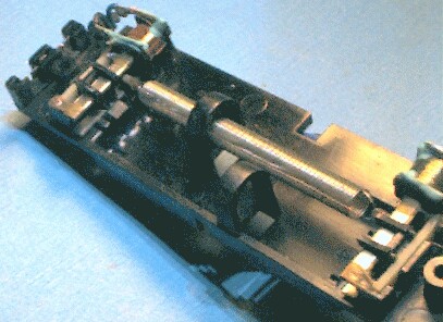
Below is the mini line, the nearer of the two springs is missing.
|
At the far end is the plate with V's where the suspension taut-wires solder. Just visible is the hair-fine suspension taut-wire itself which passes through the magnetic driver where it passes through a small (tiny) cylindrical magnet, then forms a hook to catch the end of the spring itself. This magnetic driver is as basic as they come, a coil on a bobbin slipped on a U-shaped bit of steel. In fact the only difference between the ends are the coils on the bobbins. This unit has only one spring in each run, and this passes through an anti-slosh loop to stop it twanging around too much. This is only to prevent damage. If you slosh any line enough to make it hit its protection stops the impact will launch a massive crash onto the lines, and out of the amplifier. |
|
ANZamps Date: Mon, 30 May 2005 From: Anthony Ralph Subject: Reverb tank transducer question? Group, trying to work out how the transducers in the standard reverb tanks actually articulate with the springs. |
“Actually articulate” - a well-framed question Tony.
There are three different modes a springline can be driven in:
- longitudinally (push-pull)
- radially (side-to-side)
- axially (twist)
In longitudinal mode the spring is driven along its axis producing compression waves that change the spacing of the spring turns along the spring axis.
In radial mode the springline is driven side-to-side or up-and-down producing lateral displacement waves at right-angles across the spring axis.
In axial mode the spring is driven with a rotary motion around the axis producing a change of the spring diameter.
To simply produce reverb there is little to chose between these modes, and I have built a reverb line using army surplus moving-armature headphones as the transducers in push-pull mode and it worked just fine, and you can have great fun experimenting with different springs.
That may be okay in a studio, but real reverb lines hang out in the bottom of combo speaker cabinets and the risk of audio feedback between the speakers and the springline is very real, even inside a padded bag.
If we think about it a bit we realise that the sound from the speaker acts on the springs by moving them about, just like radial modulation, so that doesn't look good.
Longitudinal push-pull looks a better prospect, but the vertical component of radial modulation by the speaker changes the weight of the spring, and so part of incident energy is translated into a push-pull. Better, but still not great.
While the spring may be moved in bulk by speaker sound there is little energy across its width to generate a torque or rotary twisting motion between the sides, meaning that an axial or twisting modulation can pass down the noisy spring in a similar way to a balanced line with common-mode noise. There is poor coupling between the modes so we have better noise immunity.
This axial, twisting or torque drive is obtained from a tiny cylindrical magnet mounted around the taut-wire suspension. This magnet is not what you expect from looking at it - it is magnetised across its diameter, not along its length. Moreover it is mounted with its poles side-to-side, not up-and-down facing the driver or pickup poles.
Looking along the suspension
When the driver poles are magnetised by driving current the attractive force acts on each side of the magnet causing it to rotate in place, thus driving the spring around its axis.
Because the Laws of Induction are bi-lateral the pickup does the same in reverse, at rest the flux from each magnet pole cancels-out in the pickup poles. When it is twisted one or other magnet pole will dominate on each side and the resulting flux change picked up by the coil.
 |
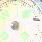 |
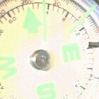
These photos show a magnet recovered from a broken line on a compass, the only difference is that the magnet has been rolled over half a turn between shots. In one shot North is attracted, in the other repelled, showing the poles of the magnet are on the sides, not the ends. A sewing needle will only hang off parts of the sides, not the parts between, nor the ends.
Some magnets are marked with a dot of paint, but be warned that this normally means “this way up”, not the North pole as is conventional, this marking being exactly half-way between the poles. Unlike guitar pickups the magnets appear to be aligned in the same orientation, not opposing.
These normally fail either electrically with a lead-in wire dropped off the back of the socket, easily fixed, or the suspension wire breaking, generally right at the back of the magnet.
I've done a lot of moving-coil meter repairs, but if anyone has had any success in repairing these without a new suspension, magnet and hook, say by gluing, I'd like to hear about it. (17/12/10: see Repairing broken lines below!)
Given these parts repair would be easy enough. Knock the solder and broken suspension out of the anchor tube. Align and solder the new one.
Experimenters who don't have ex-army headphones might think in terms of small hobby-motors, the smaller the better, with the shaft locked in something like rubber so it can twitch. Ideally connection should be made direct to the armature windings using very fine and flexable wire to avoid commutator contact problems.
See also Gibson repair.
Repairing broken lines
Addendum: 17/12/10
Prolific contributor Jeremy Shaw supplied a link to a great post on Vintage Amps Bulletin Board - Fixing Blackface Reverb Tank.
A good post deserves recognition and I think it deserves a place here in recognition of good technishing. This is one of those things I wish I had known a long time ago; that a broken classic springline can be repaired using the suspension cannabalised from a non-classic line.
|
StevenEsqThree on Sun Jan 20, 2008 7:24 pm A few months ago, I managed to score a fairly clean 65 Deluxe Reverb chassis from a guy who simply said "it doesn't work." Since it was pretty clean (and had all the original guts) I gambled $600 on it hoping the OT was not fried. When I got it, it had mismatched 6L6 tubes and was blowing fuses. After a bit of troubleshooting, I concluded the PT was blown and replaced it with a MM toneclone. With some nice NOS american tubes and a bit of cleaning up, the chassis sprang to life and was rocking.Out of sheer luck, once I had the chassis in tip top shape, an original 65 Deluxe reverb cabinet came up on ebay that had been "chopped" into a head cabinet. Cool! I had JD Newell refurb it in blonde/gold cloth and also sprang for a matching 2x10 speaker cab (had a couple of original BF logos hanging around too.) Loaded with two 1958 Jensen P10Rs (4 ohm versions), it sounds really great. Here's a pic: 
The only thing left was to find a period correct reverb unit to install in the head cab, because after all, what's a BF Deluxe Reverb without reverb right? I first tried a couple of 60s era Gibbs reverb units pulled from Hammond organs. Unfortunately, I discovered the input transducer impedence is different between the Hammond and Fender units. The Hammond units are 170 ohms on both sides whereas the Fender units are 1 ohm on the input side. The result is very weak reverb output with the Hammond units. I then found a broken 66 Fender unit. The little hook that held one of the springs inplace had broken out of its holder on one end and there appeared to be no way to solder the little thing back in place. I wondered if I could "borrow" a correct piece from one of my spare Hammond units and bring the Fender unit back to life. Here's a couple of pictures of what the spring holder assembly looks like with both hooks and both springs properly in place (taken from a Hammond unit). 
{Two other common faults; the lead-in wires fracture just where they get to the coil terminals (because it's on a spring-mounted platform and they flex a lot), and the brass collets holding the RCA socket (left) work loose, un-grounding the frame (at the pickup end). -rr} 
These are pictures of the capstan looking things that fit on the end of the transducer assembly and hold the little hooks that hold the springs in place. One picture shows a broken one and the other one is intact with the hook thing. 

How was I able to get the good one? I gently pulled it off of its recepticle where it lived on the Hammond unit with a pair of Visegrip pliers. Here's a pic with the thing removed: 
To get it off, I gently wiggled a few times back and forth, applied some pressure and it came out. I popped the good one on the Fender unit by slipping the hook thing though the open hole, attached the springs and voilla! Glorious Blackface Fender reverb! Seems simple now but at first, I had no clue as to how to remove that thing without damaging it. I first tried turning it as if it had been screwed in. No luck. I thought it could have been soldered, welded, riveted, who knows... Luckily, with a little brute force, it pulled right off. I hope this helps someone in the future with the common problem of a missing or broken spring in a Fender/Gibbs reverb unit. |
Note carefully (see above) that the magnets should be positioned so that their poles are at 90-degrees to the driving or pickup laminated poles; not facing them or any-old-how. At 90-degrees the magnets receive equal drive in both directions.
As the magnet is rotated it will first introduce signal distortion because of unequal clockwise and counter-clockwise drive producing one-sided compression, and finally when rotated to face the poles it will vibrate up and down rather than the desired twisting. At the pickup end this may result in enhanced sensitivity to undesirable vibration modes (slew rather than twist) and sensitivity to nearby speaker vibrations, possibly feedback. This applies to both ends, driver and pickup.