Variable Damping
Something to tinker with
Contains:
Why damping?
Because a speaker cone has mass it also has inertia and momentum. It resists being moved, but once moving resists being stopped again.
The cone is also a sprung system, and if deflected, energy is stored in the springy suspension. Once the cone is released the stored energy will return it to its rest position, but will overshoot back and forth several times before finally coming to rest.
For faithful reproduction of the applied signal this extra motion is not a good thing so considerable mechanical damping is applied to the cone by the suspension, mainly the accordion surround.
It should be mentioned that that this extra motion, sounds that weren't in the original drive, may actually be attractive in a guitar amp. Open-back combos were normally fitted with speakers that were fairly stiff and highly damped mechanically to start with, so fiddling with a bit of extra electrical damping isn't likely to produce much of a difference.
When we apply a signal to our speaker two things happen. Firstly the voltage drives a current which makes the voice coil motor in the magnet gap and move the cone.
Secondly, and rather more strangely, when the coil starts to move in the magnetic field it also generates a voltage. If you short-circuit a motor like this it acts as a brake, slowing or damping the movement.
An ideal voltage source has no internal resistance, and solid-state amps can go pretty close, so if we drive the speaker from a source with no resistance the speaker will see a short circuit and be maximally damped.
One of the effects of voltage negative feedback is that it reduces the amplifier output resistance to a very low value, thus giving high loudspeaker damping. A typical valve amp output resistance would be in the order of an ohm or two, a solid state amp in the order of hundreds of milliohms or less.
It is important to keep in mind when discussing electrical damping that the impedance of the speaker itself is in series with the damping circuit and so is the limiting factor. This means low-impedance speakers can attain more electrical damping than higher impedance speakers, e.g. 4 and 15 ohms.
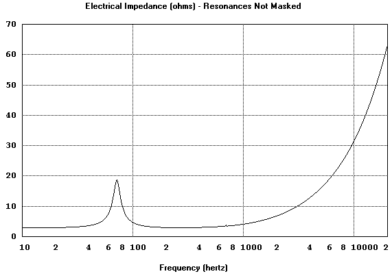
The only problem with this neat situation is that our speaker with a nominal mid-band impedance of 8 ohms has a much higher impedance down near its resonance, peaking to say 20 or 30 ohms, and as it goes high in frequency, 40 ohms and rising.

These higher impedances present a real problem for a voltage amplifier to get power into the load when it goes high-Z. This impedance also appears in series with the loudspeaker, meaning that overall damping is reduced.
Current drive has the opposite property and Rod Elliot (ESP) has suggested that there is an optimum mix of voltage and current drive that should produce flat power against changing load impedance. Keep in mind this requires a reserve of voltage headroom.
Cabinet damping
For various reasons, poor coupling mainly, the speaker reflects little of the cabinet resonances back into its electrical circuit so there is little the electronics can do about them. Amplifier damping, high or low, will have little effect on cabinet resonances or honks.
What will shut up a honky cab is a lining of acoustic wadding, but it will also make the cab sound deader.
Feedback
By far the most common form of feedback used in guitar amplifier output stages, if any is used at all, is voltage feedback. This is a sample of the voltage across the speaker and is fed back to be subtracted from the input voltage.
Strictly this is a sample of the voltage at the amplifier output, not the actual speaker terminals. This is more significant for Hi-Fi than guitar, but it highlights the fact that voltage feedback alone isn't a very good representation of what the speaker cone is actually doing.
A way that the amplifier feedback loop can be extended to include the speaker itself is by using current feedback, since the current in the voice coil is the same everywhere around the output loop and can therefore be sensed at the amp output.
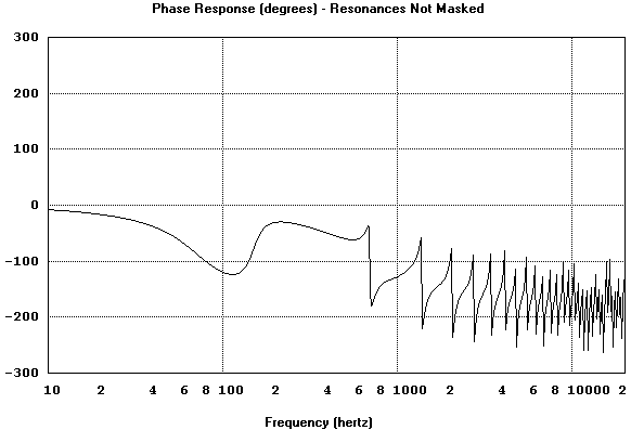
Current feedback also makes the amplifier sensible to the changing phase angle between voltage and current typical of loudspeakers, which is normally ignored.
The difficulty is that, unlike voltage feedback, the phase of current feedback with a reactive load such as a loudspeaker varies quite considerably and can easily result in instability if not carefully applied.

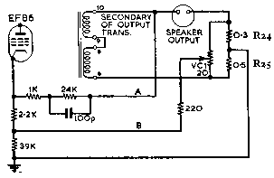
Moreover in some circuits, such as the one below, the phase of the current feedback can be deliberately reversed using the damping control.
So “carefully” meaning that current feedback is kept as a small proportion of the overall feedback level, in this case no more than one-third.
Variable Damping
Variable damping circuits were rare enough, but this one went to extremes.

Source: RCA
Normal voltage feedback “A” is taken from across the load as usual, but a very low value current sensing resistor is also placed in the speaker return. The voltage developed across this resistor is proportional to, and in phase with, the load current and is applied as feedback via “B”.
In the circuit above the current sense resistor consists of two resistors (R24 and R25) with their mid-point connected to ground, and a pot (VC1) across both for current feedback/damping adjustment, in the form of a bridge circuit.
When the pot has the same proportions as R24 and R25 the wiper is effectively at ground so no current feedback voltage is developed. Either side of this balance point a voltage is developed proportional to current, but of opposite phase polarity.
This means that the current feedback voltage may be adjusted from negative current feedback, down to no feedback at balance, then rising positive current feedback at the other end of the pot travel.
From the viewpoint of the phase inverter its return to ground is via this current sensing network which has a resistance low enough that only the voltage developed by it due to the load current is significant. The 39k resistor appears to be a safety resistor in case the pot wiper goes open.
To put in some signal levels I used the similar Pye Provost, a Hi-Fi from the 50's that used variable damping, as a basis. This used a similar arrangement to the RCA and was rated at 25W into 15 ohms, or about 20 volts at 1.3 amps.
The EF86 stage would be the phase-splitter but this could equally be applied to the more common triode-based phase splitter in a guitar amp.
The effective voltage on the EF86 cathode due to the voltage feedback is about 1.6 volts. The feedback voltage due to the current feedback is only about 0.7 volt so the voltage feedback will dominate while the current feedback adds or subtracts a portion of the total feedback voltage.
“Damping Factor”
When setting up a home recording studio...
“The first thing you need is a Damping Factor of 2000 to damp room resonances.”
This knowledgeable-sounding advice contained in an interview with a known mastering engineer is actually well-cooked drivel, or perhaps disinformation for intending competitors.
Room resonances are certainly damped by the surroundings, more by soft materials that don't reflect sound well. Naturally the loudspeaker is also part of this environment and does its share of reflecting and absorbing, but it is a tiny proportion of the entire room area and will have a miniscule effect compared to hard walls, carpet, and soft furnishings.
The implication is that if we can hold the loudspeaker cone absolutely still through the magic of Damping Factor it will somehow be capable of vacuuming up room resonances in the manner of active noise cancellation. Which is nonsense.
So what is Damping Factor and how did it arise?
Actually the basic idea of maintaining a low amplifier output resistance to provide some cone damping is not unreasonable, but like most technicalities misapprehended by the Hi-Fi fraternity (such as “skin effect”) things got a little carried away. ;)
Damping Factor is defined as the ratio of the loudspeaker resistance to the output resistance of the driving amplifier.
D.F. = Rspeaker / Ramplifier
It has been well established since the debates of the 1950's that “practical tests show that any increase of damping factor above about 20 results in little further improvement”(*1).
Most proponents of Damping Factor get uncomfortable when you mention the point that it should really be the ratio of the impedances, because then things start to get a bit complicated for your average Hi-Fi salesperson.
Damping factors in valve guitar amps may be much lower and an amp with a one-ohm output resistance driving an 8 ohm cab would only have a Damping Factor of 8/1=8.
But don't panic because there is also something basically wrong with the concept of Damping Factor itself.
One of the reasons for using lower impedance drivers is because the driver impedance appears in series with the damping circuit, and the lower the impedance the lower the total circuit resistance and the higher the damping.
So we substitute a 4 ohm cab with the same amp. Now the loop resistance is 1+4=5 ohms where we had 1+8=9 ohms before, so the damping has clearly increased. But what does Damping Factor tell us? Why that we are now worse off with a Damping Factor of 4/1=4 rather than 8. So the concept of Damping Factor can be grossly misleading.
Electrical damping of the driver is an issue, particularly in Hi-Fi, but the concept of Damping Factor needs to be treated with considerable caution and realism.
(*1) High Fidelity Sound Reproduction, ed. E.Molloy, Newnes 1958
 <<<OzValveAmps
http://www.ozvalveamps.org/varidamp.html | Last update:
22:12 24/09/05
|


