|
http://www.ozvalveamps.org/vibrators.html | Created: 24/10/09 | Last update:
19:46 17/04/2012
<<< OzValveAmps |
Okay, settle down at the back there. When these were named the other sort were not the topic of polite conversation, in fact I'm not even sure the other type even existed yet.
The vibrator was an electro-mechanical device for turning DC into two-phase chopped AC to allow it to be transformed up to generate HT for valves.
After a fairly slow start radio was becoming a mass media by about the 1920's, but rural electrification was yet to get going in Australia so manufacturers had to find ways of running sets on DC battery power which was very common on many homesteads.
In fact the remains of these DC setups can still be found on many farms around Victoria and South Australia. These followed a pattern of having a quite solid brick battery shed a little apart from the main house, with a tower alongside carrying one of the many wind generators of the day.
The acknowledged king of these windplants was the Dunlite, made for many years in South Australia until they were bought out by a multi-national and closed down. These were made in 12 volt, 24 volt and 32 volt units, and at least until the Second World War there was a thriving market for 32VDC appliances, including kitchen cake mixers, hand drills, and full-size globes.
Many of these installations grew standby 32V generator sets and were later converted to 240V start-on-demand sets. Southern Cross had for many years dominated the water-pumping windmill market and became a major supplier of such motor-gen sets.
Now DC power is better than no power, but as Edison found, transformation to a higher voltage is a problem. One early solution was the Genermotor or motor-generator set, a DC motor and high voltage DC generator wound on the same armature to make a neat little double-ended motor. The old Army No.19 set had two of these inside, one for 240V general and receiver HT, and one for the 450V transmitter final power.
Big rotary AC-DC sets are only now being phased out for tram and train traction supplies but these smaller units where pretty inefficient, and made a lot of noise, sounding like a turbine running, and generating lots of electrical hash at both of the commutators.
Big rotary sets still have application in large stabilisers and No-Break (UPS) supplies. Where good frequency stability is required a tacho-controlled genset consisting of a mains driven, SCR rectified, DC motor shaft-drives an alternator with a speed stability better than 1%.
Major telecommunications link stations such as the one in Canterbury Rd., Surrey Hills, in Melbourne employ a No-Break system that includes a triple rotary set, a very large AC induction motor driving a massive shaft with a DC motor/generator in the middle, and an alternator to feed the station at the far end (short break, within 5 mins., a long break full cycle taking over 30 mins., days of genset fuel reserve).
In normal operation the mains drives the AC motor, but the DC machine in the middle is connected to a very large battery bank, normally operating as a generator-charger, but if AC drive fails the DC machine reverses its roles and drives the shaft until the huge AC genset can start and take over AC drive again from the mains. The frequency drops 1Hz or 2% on DC power.
While the vibrator wasn't much quieter electrically it only made a gentle humming sound so was much more acceptable for domestic service.
Vibrators came in two sorts, assynchronus, and synchronus.
The vibrator is like a cross between a tuning fork and a relay. It has a large weighted reed driven by a small electromagnet. This is wired via a contact carried by the reed which is normally closed but opens as the reed is attracted by the electromagnet, thus forming a buzzer or crude mechanical oscillator.
In the assynchronous version there are a second set of contacts that are open at rest, but which switch the common pole on the reed alternately to the other two contacts as the reed vibrates (single-pole, double-throw, break-before-make). The power coming in on the pole is switched alternately to the ends of a center-tapped winding on the power transformer where the squarewave is transformed and rectified by the equipment.
Economics of consumer electronics manufacture being what they are, someone soon had the bright idea that, really, you didn't need to waste a rectifier (and its heater power, remember, no silicon diodes) when you could make a mechanical rectifier using the same reed and an extra pair of contacts.
Accordingly you may encounter radios with vibrator supplies that are only for battery use, such as old car radios, where a synchronous or self-rectifying vibrator has been used.
The advent of germanium transistors saw a few designs, and at least one product advertised in RTV&H, for a solid-state plug in replacement for vibrators.
Vibrators in 12, 24 and 32 volt gear was still around, if disused, in the 1960's, but it's very rare these days to encounter any of this technology. A few survivors can be found on the AWA page.
Something similar you are also very unlikely to encounter these days is a very similar-looking line of can capacitors (at least used in AWA's professional gear such as TV transmitters) that used a plastic base that looked almost identical to a vibrator in its socket, but they don't unplug. A vibrator will unplug with no more trouble than a valve.
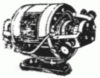
A metal cylinder about four inches high by about an inch and a half in diameter. Looks like a large can electrolytic, but plugs in.
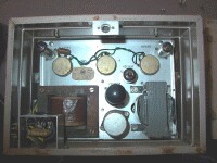
In this AWA PA828 the vibrator is the can bottom-centreTwo base styles, two fat pins plus three (assynch) or five (synch) thinner pins (similar style to 807 basing).
It will have heavy wires going outboard for DC input, and a couple going to the power tranny. A sync. type will also have wiring to the high voltage side.
Should have some large supression capacitors (typically waxed paper), and possibly small heavy inductors, around the base.
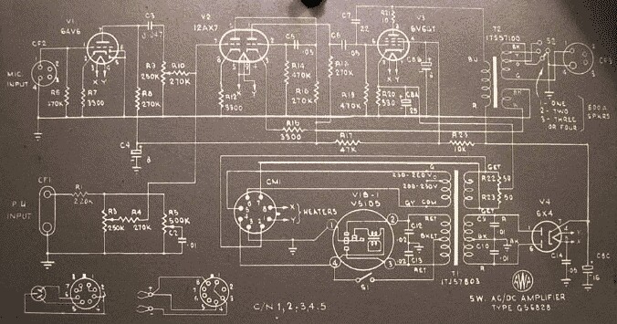
AWA PA828 Circuit diagramme. Four pin assynchronous vibrator VIB-1Photos: Evan Lorden
The assembly is held together by a wire circlip inside the base lip which is easy to remove once located.
More difficult is a thick grounding tab soldered to the case. This has to be unsoldered but requires a seriously brutal iron such as a Scope.
The problems with these are identical to car ignition points - pitting. In mild cases a burnish with the edge of a newspaper page ( a good starting point for any contact cleaning) is a good place to start. But you will often find that more radical treatment with a points file is required. In this case be prepared to spend some time with the CRO tweeking the contact positions to regain proper switching timing.
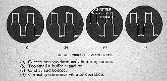
Note carefully the tapered mid-section, “crossover distortion” or non-overlap, where both contacts are open as the reed passes through its centre resting position. This short rest between reversals greatly reduces arcing at the contacts.
The last example shows the correct timing sequence for a synchronous or self-rectifying vibrator; the low voltage drive should connect just ahead of the HT rectifying contact, and should break just after it - i.e. the output is only connected during the drive flat-tops.
|
|