|
http://www.ozvalveamps.org/ava100/ava100harp.html | Created: 17/06/09 | Last update:
23:29 22/06/09
<<< OzValveAmps |
I emailed Roly around November '08 about building an AVA100-inspired custom blues harmonica amp for a friend. I finished it just before Christmas last year and the friend that I made it for has been using it at home and at a weekly blues jam since then.

Craig's Harp amp circuit (400kb)It's a 15W 1x10” combo with a quadrupler HT power supply, 6V6 output valves, and Altronics P.A. transformer. It also has a 5 Meg AC coupled input impedance for a crystal harp mic, unbalanced phase inverter for some second harmonic distortion into the power stage, B+ bleed resistors, and Dana's VVR (variable voltage regulator as posted on 18watt.com (*) and other amp forums) to control the output power from 15W down to under 0.1W.
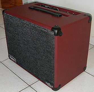
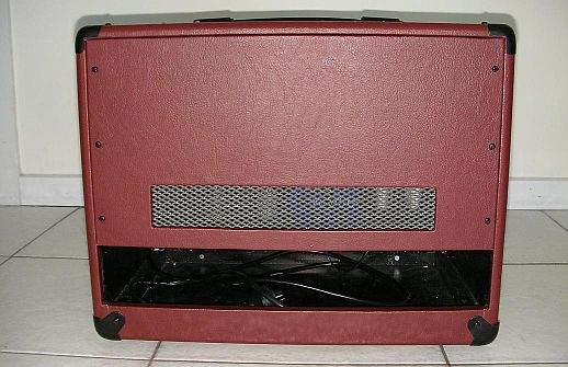
The cabinet is partly open backed and loaded with an Eminence 10” Rajun Cagin speaker (a speaker that is not as bright would be better, but that was the only high sensitivity 10” Eminence available in Aust).
All parts and materials were bought at retail stores apart from the valves and the speaker, which were both bought online from businesses local to Melbourne, and some of the supply caps which were out of used disposable cameras. Retailers for all the parts were Jaycar, Dick Smith, Altronics, Bunnings, Essential Audio, ebay Tube Amp Shop, Ullrich Aluminium, Vyfab (can also get limited range of vinyl from Clark Rubber) and Spotlight.
All up cost was just over $500, but this was before recent price hikes and some item costs are now a bit higher. Replacing the 10” speaker with a 12” would bump this up to $550 - $600.
At first I used the string of 6x1000uF 63V caps on the quadrupler supply output. I found that this gave 310Vdc and powered the amp well. But with the inclusion of the VVR, as you turn down the HT voltage, less current is drawn from the supply and the voltage goes up. Without the VVR it wouldve been fine as even with the ripple it is not near the combined rating.
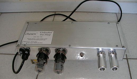
But with the VVR turned down it was getting uncomfortably close to the rating of the string of caps (373V with 378V rating) so I replaced them with the caps from used disposable cameras. My local camera shop was more than happy to hand me a bag full of them. It didn't take long to discharge and recover the caps (did find one with 300Vdc on it still!) and I ended up with 4x160uF, 4x120uF & about 15x80uF all rated at 330V. I used two sets of 2x160uF & 1x80uF paralleled as shown on the schematic. Rating across the set is 660V and I'm much happier with that.
All power and output transformers run quite warm but not hot enough to cause any concern.
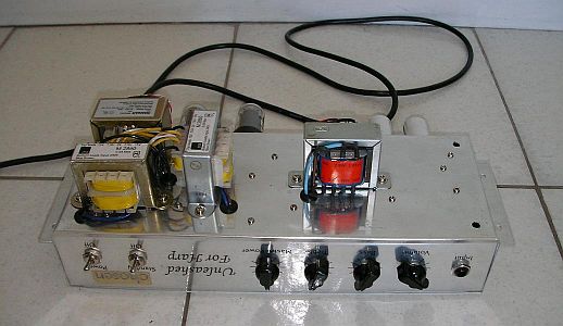
Full size photo of underchassis detail.
The chassis is homemade out of 1mm aluminium, and is time consuming to make. Panel design was printed on paper, stuck with glue stick to the cut sheet, and drilled with a step drill bit and cut with a jigsaw before bending. If you're careful, accurate bending can be done with cut to length angle iron and clamps - you don't need a sheet metal brake.
Almost as time consuming is the cabinet which is MDF, fully sealed with black acrylic paint and vinyl covered. The wiring is the quick part of the project.
The power indicating light logo is etched brass shim using the same toner transfer method I use for making my own printed circuit boards. The front panel artwork is printed on overhead transparency and sandwiched between the aluminium and a drilled panel of clear acrylic. I have also seen good results of printing to quality paper or gloss sticker sheets to give a white or coloured background behind the acrylic panel. Top and back grill are cut from gutter guard from the hardware store.
The online diy community (including AVA) has given me so much that I am happy to openly share the harp amp design. I only ask that the brand “chosen” is respected as TM and that the model name “Unleashed For Harp” is not used by others for their amp. They can feel free to use my circuit or any part of it and give it whatever other name they want. Hopefully I've also given some construction tips that others will find useful.
I've included a full schematic, photos and a couple of sound clips (recorded with my camera so not mixing desk quality) from a jam night at the Nighthawk Blues bar.
Sound clip 1 (MP3, 1.4Mb, 1:14)
Sound clip 2 (MP3, 600kb, 0:30)Cheers,
Craig.Out of respect for Craig's naming wishes, builds of his circuit may be identified as AVA101-3 Harp. Perhaps this is the right place to remind readers that all of the AVA100 designs and names are copyright, and that you have release to make personal use only of this information. Commercial use is forbidden without a licence agreement (com'mon MickySoft, I dare you; I'd settle for only 10% of $500mil :).
“chosen” as a marque, and “Unleashed For Harp” are specifically copyright reserved.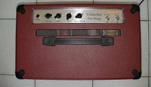
(*) note: http://www.18watt.com/ and http://www.45watt.com/ are specifically Watkins/Marshall forums (registered users only). 18watt is reportedly defunct, but general push-pull and single-ended forums are being continued as http://www.ppwatt.com/ and http://www.sewatt.com/.
An input-to-output outline of the changes Craig has made to the basic AVA100 circuit to customise it for Blues harp.
But first, a basic acoustic concept. An engineer might look at a harmonica and think it needs an amp optimised for its primary frequency range - in a word “trebly”. But the experienced soundie knows that the strengths of any instrument speak for themselves, and it is the low woody tones of a violin, or the delicate upper harmonics of a double-bass that you have to struggle for. Take care of these things, and the rest will take care of itself.
This leads to a Rule of Opposites where you use hard mikes on soft sources, and soft mikes on hard sources. Harp players have come to favor piezo microphones despite them typically having quite a hard, even harsh, sound; but unlike the more common dynamic type, they are better suited to close/intimate harp playing because they are hard to overload (just producing a volt or ten of signal!) and more resistant to moisure damage.
So a harp amp has to be doubly soft - once for the harp, and again for the piezo mic. Accordingly Craig has spread top-end rolloff through the whole amp, and this should suit other applications such as a violin or guitar with naked piezo pickups.
I want to put in a word here for the humble $2 electret capsule. I have done a fair bit with these and if the supply voltage is near maximum (say 9V) they are flat, very wideband, and almost un-overloadable. Most of their shortcomings arise from being driven by too low a voltage, only 1.5 or 3V.
The Chase
The amplifier input impedance has been significantly increased to 5 megs to better match the high impedance piezo microphones popular with harp players. While piezos generally work best into 2 megohms or more, some may actually become boomy with a 5 meg load. If this is a problem the two 10meg input resistors can be reduced to around half their value, giving an input impedance of around 2.5megs. (the traditional value for piezo pickups is 2.7meg)
The first valve has been changed from a 12AX7 to a lower gain 12AY7 (basically an audio version of the VHF 12AT7). As a result the front-end “gain” control has been dropped. My original first stage design proved to be a bit of an overcooked Gain Godzilla so the shredders would have something to play with, but not really what you want with harp (which naturally has high orders of distortion). A 12AU7A would calm it down even more.
The anode loads of the first two stages have been reduced to 47k and each bypassed with 1nF giving some top-end rolloff. The steeper loadline should give somewhat better linearity (less stage distortion), while the cap will also help overall stability.
The tonestack has been split leaving the bass control in the original position, but moving the treble control to the output stage.
The phase-splitter has been changed from the single section split-load type to the double-section cathode-coupled type.
The treble control is now a top-cut type across the phase-splitter output, and some fixed top-end rolloff has been fitted. This has implications if you want to apply NFB around the power amp stage - basically you can't - unless the treble control is first removed to before the NFB loop. (e.g. see Strauss - Early 60 watter)
The 6V6 output stage is conventional except that it has no negative feedback. If feedback is desired then it would be a simple matter to apply it to the phase-splitter, either via the (AC) grounded grid, or in the cathode circuit.
The 270ohm resistor is to provide some protection against being driven with no load (i.e. the speaker disconnected). This is a good idea with any amp of this class.
The solid-state power control is a series pass voltage regulator. (a dead computer power supply or CFL may provide a suitable FET).
One rather cunning trick is the use of a Double Pole Double Throw standby switch with the extra contacts used to connect a bleeded to the HT line and pull it down rapidly when the amp is placed on standby.
15W is good enough to play on stage, but if anyone wanted an amp to just play at home, 1-2W through an efficient guitar speaker is still loud enough to get any close neighbours restless and would be a very cheap and small unit. It would be a power stage basis for the number of 6SN7 or 12AU7 amp designs on the net like AX84's 2W push-pull poweramp with any of their preamps, Firefly, Moonlight, 4-4-0, TMI's 2W SLO, the DennisF 1.8W Lite, etc.
Output transformer is the newly available Jaycar MM1900 or you can use the very similar Altronics M1109, both giving a plate-plate impedance of 20k with an 8 ohm speaker load which suits the 6SN7 pair nicely.
I'm building this as a small head amp because I have a couple of different speaker cabs at home. First plan is to build a 1.8W Lite for side by side comparison to my 18 Watt head, and then I want to try out the 18 Watt TMB based options, a Plexi preamp, JCM800 preamp, and Trainwreck / 4-4-0. I'm not likely to build a combo unless it's for someone else, but also imagining it could also be nice as a small 1x8” practice combo with a Celestion Super 8 and spare switching jack to allow plugging into a larger external cabinet.
Power supply - Looking ahead
Craig and I have obviously been following parallel mental paths about the need for a -ve bias supply in bigger amps. Was an extra lighltly-loaded voltage multiplier stage connected to pump down going to work? But he actually did something about it first:
Expanding on the quadrupler, I had an idea about a HT supply for fixed bias push-pull. If you add another doubling stage on the grounded end of a quadrupler or octupler circuit with the standard resistive divider and pot it will generate a negative voltage for a fixed bias supply. I simulated this in Orcad and it seems to work fine. The bias supply is lightly loaded and doesnt seem to upset or unbalance the quadrupler or octupler circuit.
I have now started building a guitar amp with a 6SN7 based 1-2W push-pull output stage with a different AVA inspired power supply. Once again, any type of preamp could go in front, and I'm going to be using this as an experimenters amp to try out a few common amp configurations for my own interest.
I started thinking that because of the lower current required, a voltage octupler could bump up a single 30Vac transformer to around 300Vdc. Then with one rated at 1-2A with multitaps and an unbalanced octupler circuit (with three doubling stages on the upper half and only one doubling stage on the lower half) it would put the 30V tapping at 86V unloaded or around 80V loaded.
Then the 24V-30V tappings can be used to supply 6.3V heaters or 17.5V-30V tappings for 12.6V heaters. The elevation doesn't exceed the rating of max voltage between cathode and heater for either the 12AX7 preamp valves or the 6SN7, and gives an elevated heater supply, but with some ripple on the elevated reference.
The normal balanced octupler would put the 30V reference tapping too high and heater to cathode voltage peaks are getting close to the 12AX7 rating and definitely exceed the 6SN7 rating. I'm hoping because of the elevated supply the ripple on it's reference tapping won't translate into hum from the heater to cathode of the preamp valves, and it should be mostly cancelled in the power stage anyway.
Sizing the octupler capacitors would dictate the amount of B+ sag as the amp is turned up without using a sag resistor. More filtering gives a stiffer supply but a slower power up.
I've included a schematic of the unbalanced octupler idea with the values I am using.
Caps are once again just what I got from disposable cameras and are rated at 330Vdc, and ideally I'd bump up the 4x120uF caps to 160uF for a bit better regulation and slightly higher output voltage.
With the values shown in the attachment an Orcad simulation shows I'll get a B+ of 328V with 2Vp-p ripple at bias load with no signal, and 287V with 5Vp-p ripple with the output stage into full overdrive. The sim also shows that powerup takes about 1 sec, the ripple on the 30V tapping elevated heater reference is 2.5 Vp-p with no signal and a bit under 7Vp-p at full overdrive, and from no signal to full overdrive the bias output moves less than 0.5V and has around 25mVp-p of ripple.
With the 160uF caps the sim shows a B+ of 330V with no load and 294V at full overdrive - slightly better regulation for the effort of picking up some more used cameras.
|
|