|
http://www.ozvalveamps.org/ava100/ava100robslamington.html | Created: 15/09/09 | Last update:
18:57 15/12/10
<<< OzValveAmps |
The idea of building a small valve based guitar amp has appealed to me for some time.
I finally got around to it and this is the story of that 6BQ5/EL84 build.
Being a working Guitarist, I like simplicity when I'm on stage. I don't use effects pedals or racks full of pre-amps. (I don't even use a pick. Very much the Jeff Beck school of guitar playing.)
I also LOVE simplicity when it comes to load-ins and lug-outs. Dragging a great 100 Watt behemoth and a quad box about gets pretty old pretty quick when youre on the road.
Add to that, the noise level regulations in most venues these days really don't allow for an amp at full tilt. ANY amp. A Peavey 5150 with the Volume anywhere past about 3 will get your bandmates offside and anywhere over 5 will get you evicted.
Enter the AVA 100 Project. Grant's Lamington project and Roly's excellent information spured this build on.
All parts (except for the M-1130 Output tranny, the voltage doubler caps and the valves themselves) were purchased off the shelf at Jaycar.
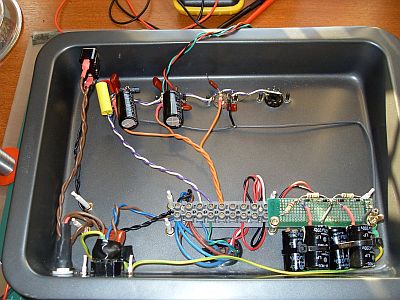
I chose to build my amp point to point. This was new ground for me. It's a very different construction technique from the PCB's I am used to, but I think it gives a much better understanding of the schematics and operation of the circuit. Kind of a more intimate feel about the whole build. It gives the build a much closer relationship to the schematics. I think it makes trouble shooting and modification a lot easier too.
I still feel my wiring could be neater. The next one will be Im sure.
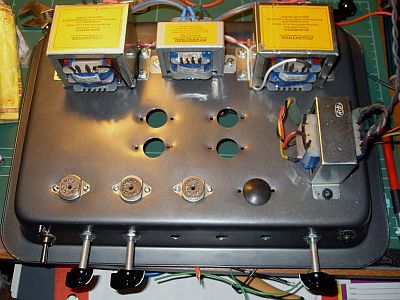
I used a baking tray for the chassis. I had to buy an up market unit that cost me $10.00. Wiltshire brand trays give the best tone. This was concluded from extensive in-house testing by my own group of class leading sciencetitians using state-of-the-art proprietary analysis methods and a fair amount of conclusion jumping.
** NB. These results are based on subjective interpretation and may vary depending on your concept of reality and basic physics **
I drilled the holes for the valve sockets using a 20mm hole saw. K-Mart sometimes carries them or Bunnings if you prefer. Perfect fit for Jaycar's 9 pin sockets. (12AX7, EL84, etc)
If you need to use the larger Octal socket (for 6L6's etc) a 32mm hole saw will do it but there's not a lot of room for error as the socket mount is only just outside the hole on 2 sides. 30mm would be better if you can find one.
Comment: The ceramic sockets from Altronics are nicer looking and electrically slightly better than the more conventional ones from Jaycar, but they have less latitude on the size of the hole and require a nice clean edge; difficult if you have limited tools. With rougher holes the Jaycar sockets are more tolerant and can help hide a rough hole.
To make all the required holes a step drill is a good investment. Jaycar sell two size ranges but Bunnings sell a single 10mm to 30mm x 2mm steps for about $25 (Sept '09), but note that the Bunnings step drill does not make the right size hole for the ceramic sockets. While these work okay in a hand drill, Bunnings also sell a Chinese drill press for $100. Obviously this is only a light duty machine but for the price mine has been satisfactory for drilling PCB's and chassis' -rr.
I put two blocks of scrap wood under the tray to support it while I drilled the holes. Place them either side of where the auger will penetrate and use a fast speed on the tool. If you cut too slow it WILL bind and bend the tray just as it cuts through. The scrap circle that comes out will be BLOODY hot and razor sharp, by the way !
DO NOT use the hole saw without the central auger bit fitted. It will run all over the place on you.
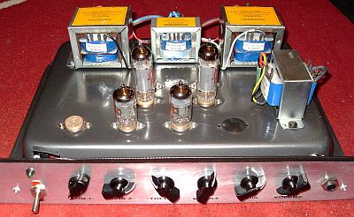
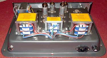
The rest of the construction was pretty much the same as Grant's. I placed the two power transformers at opposite sides at the rear of the chassis to spread the weight more evenly.
The heater supply transformer I placed between the power transformers. M-1130 output transformer was ordered from Altronics and shipped next day. Excellent service.
IMPORTANT!
***** The output transformer is placed 90 degrees to the power transformers to limit induced hum. ******I don't know if this has been stressed enough. If you place the output tranny in the same orientation as the power transformers, you WILL get hum in the output. No if's and no but's. I have tested the transformer placement with my own unit and the hum increase is VERY noticeable.
Comment: to test this for yourself, after you have mounted the power trannies and mains wiring but before you mount the output transformer, connect a 'scope or pair of headphones to the output tranny speaker winding, apply power to the mains trannies, then move the output tranny around near its desired mounting position for minimum hum - that's your mounting position. -rr
The Output transformer is wired as per the following.
Primary (Valve) side
“Com 0” to left hand side (viewed from front) output valve anode
“5Watt” tap to right hand side output valve anode
“20Watt” tap to 310V B+Secondary (Speaker) side
for 8 Ohm cabinet
“Com 0” to Speaker ve and Gnd, “2 Ohm” to Speaker +ve
for 16 Ohm cabinet
“Com 0” to Speaker ve and Gnd, “4 Ohm” to Speaker +veComment: this is not an error, the wiring of a typical 8 ohm cab to the tap marked “2 ohms” (etc) is quite deliberate to obtain the higher impedance required by the valves on the primary. -rr
I plan to make the output side of the tranny externally switchable for 8 or 16 ohm loads as I have different cabinets that get employed at various times.
Power supply
The Power Supply was the first step.
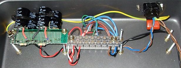
I followed Roly's Phase 5 design, utilising Capacitors salvaged from PC PSU's. (Nearly every other piece of wire used throughout the build came from the same dead PSU's.)
As Roly said, they are a FANTASTIC resource.
The power supply is pretty straight forward and gave no build problems. Except for this.....
Salvaging from dead PC power supplies is a great idea. However, it turned out that the bridge rectifier I had salvaged to use was the root cause of the PSU's death in the first place. Had I not checked the component first, It may have taken a while to find the problem.
The lesson is to remember that the donor supplies were dead for a reason. Check anything you salvage. Especially the big 200V Caps we want for the power supply.
I have since found several other faulty bridge rectifiers. All of them shorted. It may be “failure of the month” at the moment. Not so long back it was the “Great Capacitor Swindle” causing most of the grief.
I ran my 240V (except Earth), heater and PSU connections to a screw terminal strip mounted across the heater transformer mounting bolts.
The screw terminal strip made it simple to connect or disconnect various circuit segments for testing. It will also pass any certification scrutiny (in Queensland at least) if you need to have the finished unit tagged. I have had this done as this amp will be used on stage and therefore comes under the classification of “electrical plant” and needs to be tagged so as not to void any public liability insurance.
Make sure that there are no exposed conductors (wire strands) protruding from the screw terminal strip and DO NOT solder the bare ends of the mains that will go into the terminals. You have to let it crush. This is good practice even if you only use the amp at home.
Comment: the reason is twofold, firstly solder-tinned wire cold-flows under pressure leading to the connection working lose over thermal cycles and creating a potential hot-spot. While this is unlikely to start a fire in an amp it can lead to crackles, zapping, and intermittant operation. The second reason is that solder embrittles copper, so you will note that wires frequently break just where the solder stops, where the copper is still embrittled but not supported by the solder. -rr
The power supply was fired up and tested.
2x M6674 30v 60VA trannies wired in series for 60V feeding the charge pump circuit. 375 Volts no load. Cool! So far so good. Further load testing was done later using incandesent globes.
My figures were very close to Roly's. 347V @ 300mA continuous. Well and truly above what we need for 2 EL84s at full output.
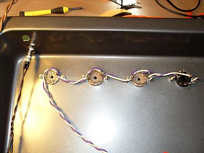
Heater wiring was next. I followed Roly's information on heater wiring here. Nothing too complex, but I found it a little tricky to keep neat and tidy. Second time round was better. Not brilliant, but better.
Comment: while this was sufficient for this build I suggest a tighter twist, say about one twist per cm, and a bit more spacing from the valve signal pins where it goes past. -rr
If you use Jaycar's valve sockets, be careful with the length of the mounting bolts. These will pass RIGHT by pins 4 and 5 on one side and pin 9 on the other. It is possible to inadvertantly short your heater circuit to a mounting bolt if the bolt is too long. I used the shortest M3 (3mm) fastener I could. With a shake proof washer and nut, it is just under the level of the pins. I put some heatshrink over the nut and bolt as well.
Comment: I use short lengths of plastic wall plugs over the threads to insulate them from accidental contact, to act as a keeper for the screw and nut should it come lose, and to stop them biting your fingers during construction. -rr
Remember that we are dealing with a steel chassis and not a jiffy box. So even though we are running all our grounds back to one point, every other point on the chassis is still going to ground, so anything conductive like screws and bolts through the chassis are also going to ground.
Hindsight tells me to put the bolt in from the bottom with nut on the topside of the socket. Not as pretty from the outside perhaps, but I prefer function over form if I have to choose.
The metal chassis is also something to consider when we mount our input and output sockets. The metal threaded ones will ground through the chassis and not at our ground point. We don't want this. The point of the “star ground” (a.k.a. Single Point earthing) is to eliminate earth loop problems that will show up as hum. In order to avoid earth loops, we must have ONE and ONLY ONE path to ground.
This is a concept completely foreign to automotive electricians. Cars have more ground connections than you poke a stick at. This is why car tail lights start behaving strangely. Suddenly one lamp becomes a route to ground for another. Or the clock only works when the door is open?!?
Sometimes you have to visually check your layout to make sure that there is only one path to ground. If you lift your star ground point connection, there should be no continuity between any component ground and the chassis.
Comment: this is also true for aftermarket car sound systems that should have their power feed and return run directly to the battery, and not connect to the car body anywhere.
Make sure that the mains earth is constantly connected to the chassis at your star ground point and cannot possibly disconnect. This is going to protect whoever is hanging off of the guitar at the other end if a fault develops. We dont want another Keith Relf (Yardbirds) incident. (or Stone The Crows Les Harvey, or The Shadows John Rostill)
I used plastic bodied sockets. Not as robust, but I can be certain there are no ground loop issues without trying to insulate a metal thread.
Check the heater wiring for shorts to the chassis before connecting to the transformer.
Preamp
The preamp circuit was next.
No real changes to Grant's. 100nF 630v inter-stage coupling caps instead of 22nF in the preamp stages. They were to hand at the time.
1 watt carbon resistors throughout. Again, because they were to hand. I have since tried ½ watt metal film resistors throughout and I can't spot any difference.
I opted for a 3 band tone control and added a “Gain Boost” footswitch arrangement. The tonestack is pretty much the same as Fenders. The “gain boost” arrangement is borrowed from Mesa/Boogie.
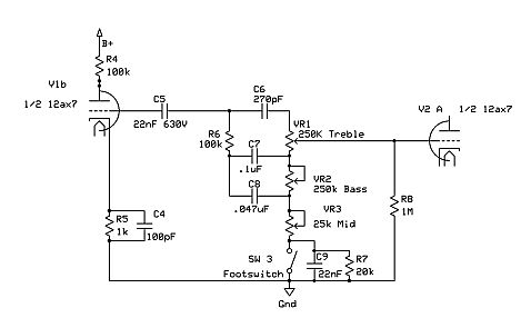
It basically lifts the tonestack ground thereby defeating the tone controls and putting back any insertion loss that is inherent in the tonestack. At least, that's my understanding.
I chose the value of R7 to give a volume boost that suited my taste. C9 helps get rid of any click on switching and Roly suggested the use of a ferrite bead or wrapping the switch lead a couple of turns through a ferrite ring to get rid of any induced RF. This works nicely. No clicks, no noise. I use a shielded cable to the footswitch, grounded at the amplifier end only.
VAS, PI, and Output
Voltage amp and Phase inverter was next. No changes from Grants Lamington. Straight forward.
Output Stage is, again, no different to Grant's.
Voltages were checked at valve sockets prior to plugging in valves.
I brought my amp up in stages testing as I went with a scope on the output of each section. Power supply, Preamp, VAS and PI then the output stage.
I also tested the preamp stage and tonestack output by connecting the 22nF coupling cap to another amp.
I breadboarded the tonestack at first and ran short flying leads in and out so I could easily change cap and pot values. Duncan's tonestack calculator is great, but I need to hear it for myself.
Just make ABSOLUTELY certain you are on the DC-decoupled side of the cap from the 12AX7 anode. Remember the anode is at HT potential!!!
Once I was satisfied that everything was where it should be, it was time to plug in some output valves.
The cheapest option I found for 6BQ5's/EL84's was RS Components @ $18.20 each. Again, next day shipping. Excellent.
There are probably other suppliers but whatever you do, don't buy from Guitar shops. I had prices anywhere up to $79.00 each for the EL84's and up to $39.00 for a 12AX7!
I opted for a pair of JJ Electronics EL84's and a couple of Sovtek 12AX7's. I'm not convinced that there is a lot of difference, sound wise, between different brands of valves. I have tried various brands of 6L6's and 12AX7's in my other rigs and I am hard pressed to hear anything different. Maybe I'm missing something though. Perhaps in Ultra Linear HiFi amps it makes a difference. I dont know.
If you want to (or can) spend $145 per valve on some New Old Stock (“NOS”) Mullards from 1962 or whatever, please go right ahead. For us mere mortals, the Russian jobs are fine.
I have had problems with longevity of some Chinese 12AX7's in the past, but that could have been due to any number of factors. Rough handling, bad batch, etc. My amps spend a lot of time in the back of a van on Queensland roads, so it's not really surprising to find a failure or two.
Comment: I strongly suggest that builders start with cheap valves until they are satisfied the amp is working correctly before experimenting with more expensive valves looking for tone. If there is a wiring error it is much less painful to blow up a cheap valve, and the tone may prove satisfactory anyway. -rr
Testing
Double checked EVERYTHING before firing the amp up.
TRIPLE checked EVERYTHING.
Found a couple of wiring mistakes in the output section. Namely, forgetting to tie one end of the speaker output to ground.
Quadruple checked everything.
The first fire up was done with a dummy load of 8 Ohms, a function generator and a 'scope. All of these can be built at home too if you're a broke muso like myself.
Test gear
DOS based PC scope software
I built the LPT MUX interface to use with a spare laptop.
Simple XR2206 based function generator circuit - this is in German but youll get the idea
Rolys own dummy loadPower on and check for anything unusual. Transformer buzz, smoke, people screaming, things like that.
I set a 500mV p-p signal @ 1 KHz on the function generator and brought up the gain and volume on the amp. I got a nice sine wave appear on the scope.
Increasing the gain is where I found it breaking into oscillation. Fitted a 100 pF bypass cap across the second pre stage anode resistor and tried again.
This time all was good right up to full unclipped output of 31.5V p-p. Shut down, rewired the output tranny for a 16ohm load plugged in the quad box and my Telecaster.
A couple of hours later I turned the amp off. :)
Amp Case
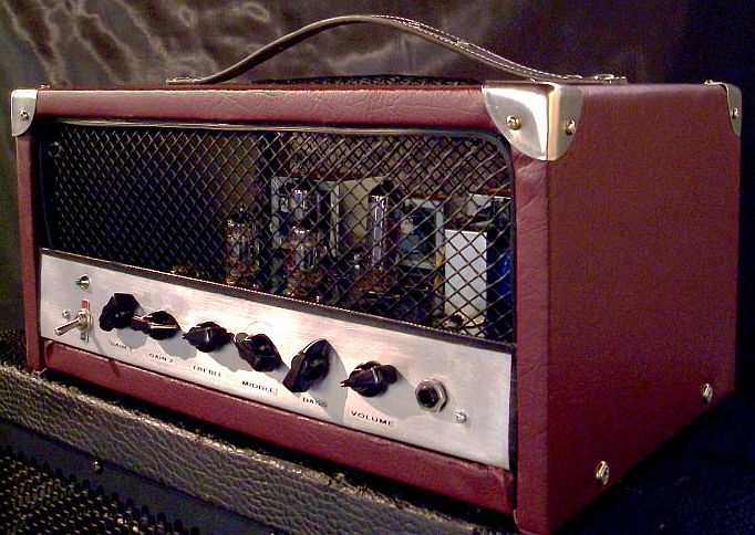
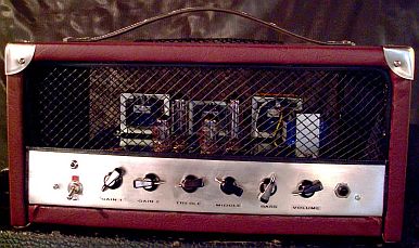
Then it was time to build a box of some sort for the amp. I built mine into a “head” type enclosure as I need the flexibility of different cabinets depending on the gig or the venue.
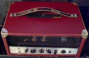
I used some MDF that used to be a TV stand. Covered it in Vinyl from a local Spotlight fabric shop at $14.00 per meter. 1 metre was more than enough and they had a number of colours to choose from. It is attached with spray adhesive and a staple gun.
Comment: when working MDF (or any fiberboard) protect yourself from the dust - it's toxic. -rr
My Fiancée chose the colour and covered the MDF for me. She did a far better job than I would have.
The top strap handle I made from a 1 inch wide, $2.50 leather dog collar I found at a Bargain City shop.
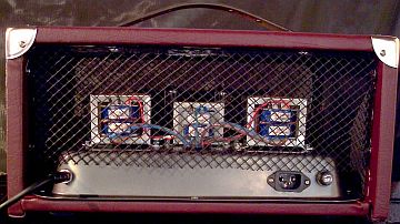
The front and rear grill is plastic gutter guard from Bunnings. I think it cost about $3.00 for about 8 meters of the stuff. I wanted aluminium mesh but I couldnt get hold of any. Metal case corners were about $5.00 from a hardware shop.
Aluminium sheet for the front panel from Bunnings 300mm x 900mm x 0.5mm cost $12.95. I used 1 section doubled over for rigidity. I couldnt get any 1 mm Aluminium at the time.
The sides were also bent over to further support it, then bolted to a right angle bracket at either end. The pots are actually mounted to the baking tray chassis so that the shafts protrude through the front panel. I had to bend the front of the baking tray a little so that the pot shafts sat horizontal.
Comment: any metal panel like this that carries a mains switch or fuse, and that is not part of the chassis MUST have a secure earth wire back to the central earth point for your protection. -rr
I labeled the front panel with a Brother P-touch labeler with black on clear tape. (I need to re-do these as the tape I used was quite old and is already peeling up at the edges.)
The enclosure took longer to build than the amp itself !
|
|