http://www.ozvalveamps.org/ava100/ava100project.html | Created: 18/10/06 | Last update:
13:11 10/01/11
<<< OzValveAmps
|
AVA100 Series amp projects
A Co-operative “Open-Source” Design Development.
Build your own guitar amp
- save heaps of money and get an amp that's more than the equal of anything you can buy.
Contains:
This page - project discussion;
- Preface
- Preamble
- The Design Process
- Amp design constraints
- Introduction
- Modules - build Status Board
- The Case
- Speakers
- Process
Other pages - grounding the ideas;
- AVA100 main power amp
loadlines, power, distortion, cathode circuit, screen circuit, phase inverters, NFB
- AVA100 power supply
worked examples for small, medium and maximal, bias, thermo-fan, solid-state.
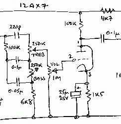
- AVA100 preamp, EQ
a simple front-end with heaps of gain and radical single-knob tone control.
- AVA100 General Chassis v1.4 080820
- Old ATX PSU's (and disposable cameras) for Free! amp bits
- Packaging - a look at various cases and ways of assembling a raw amp into a functional gigging amp package.
Actuality;
|
Modules
Moved up page: 14/12/10
Note: valve rectifiers are not suited to voltage-multiplier applications because each requires an isolated heater supply. More conventionally they require a high-voltage power transformer. If you happen to have a suitable one, by all means use it, but as they are not available over the counter they fall outside our primary design constraints, so valve rectifiers are NOT available as an option in this series of amps. (but if you do build one, by all means submit it).
| STATUS BOARD key: |
Built |
Building |
Open |
|---|
| | | |
| Power supply |
heaters | HT | bias |
| PSU options |
minimal 30W |
middi 60W |
large 120W |
maximal 300W |
| Output valves |
6BM8 |
6BQ5 |
6GW8 |
6V6 |
6L6 |
6AQ5 |
6CA7 |
6146 |
| O/p transformers (W) |
15 |
20 |
40 |
50 |
40+40 |
| O/p ohms |
2 |
4 |
6 |
8 |
16 |
| O/p power (W) |
10 |
15 |
20 |
30 |
40 |
50 |
60 |
| Mode |
triode |
ultra-linear |
pentode |
| Feedback |
none |
voltage |
mixed V-I |
| PI |
Split-load |
balanced |
voltage-inverter |
leaky-grid |
transformer coupled |
| Preamp |
12AX7 |
12AY7 |
1/2 6BQ5 |
1/2 6GW8 |
EF86 |
6BL8 |
| Tonestacks |
1 knob |
2 knob |
3 knob |
parametric |
| Trem/Vib |
AM LDR |
AM mu-mod |
FM Phase-mod |
DSBSC o/p bal-mod |
| Line Out |
unbalance |
balanced |
| Reverb |
drive |
recovery |
| Put your hand up for one of the open builds |
Notes: 22/7/09
A Particular Caution
 The cans of the capacitors used in the voltage multiplier must be assumed to be live, and should be suitably insulated against accidental touching or contact with each other. With the centre-fed multiplier the transformer secondaries are also “live”.
Experience So Far
Almost all the problems encountered building these amps have been due to layout. If this is anything like your first valve build stick to the layout shown.
The most likely causes of hum or instability are not following these guidelines. Also note that for best results the open chassis bottom also needs to be screened. The best thing is a metal base, but some manufacturers have glued alfoil to the inside of the wooden case under the chassis. These days we can insulate and protect this with a layer of self-adhesive sheet but we need to make a good electrical connection to the chassis earth point.
Please report any errors you find (and thanks to those who already have).
I built my first guitar amp in the 60's when I was an impoverished teen schoolie.
This design is based on the belief, and demonstrates in fact, that you still can.
Note carefully: like any real-world tool that is actually useful this amp isn't a “safe” project. It runs off 240 volt mains power and generates high voltages internally - if you do something stupid it could kill you and bring your musical career to a very abrupt halt.
Since I have no control over what you do I will accept no responsibility whatsoever if you blow the house fuses, zap yourself, burn your house down, or suffer any other disaster, loss, or injury as a result of reading these pages. I might send you a “get well” card, but I wouldn't bet on that either.
That said, everything we do contains risks, and building a guitar amp is a lot safer than messing with explosives or rocket fuel. In fact I'd rate it as safer than skateboarding, riding a BMX or motorbike, or even crossing the road. If you read and heed all the warnings, use commonsense and don't do anything stupid, there is no reason why you can't end up with a guitar amp that will serve you for many years.
All the amp designs presented here are push-pull due to the difficulty and expense of obtaining single-ended output transformers. If you really want single-ended designs I suggest that you look at the well established AX84 project.
Note: the 6GW8 isn't being currently manufactured, so where you see “6GW8” just think “my favorite pentode”.
The AVA100 developed below should be considered a theoretical mind-amp, a thought-experiment investigating the bits and moving them around before actually getting down and dirty with construction. As parts are built and reported they will be published here.
If you are new to DIY electronics you are strongly advised to read and understand all the AVA100 pages before buying anything or commencing any construction.
Addendum 20/6/09 - If you are a newby you must read some background articles as well so you better understand what you are doing, particularly if you are thinking of changing anything such as the component layout; first read mains, heaters, grounding, and for background output trannies and amp stages. It may not be obvious but these amp layouts are the result of very considerable thought, so if you change the position of something then freedom from instability, noise, and hum, cannot be assumed. First you copy, then you take Berlin.
If you are still unsure about any aspect, or think you've found a mistake, please feel free to write to me (or the author) with any questions you may have.
If you are already experienced, very keen, or just desperate, and want to have a go right away and don't mind a bit of adventure, then jump right in. I'd love to hear your results and particularly any problems, but please don't complain if something is specified that later turns out to be a doorstop.
You want certainty? You're on the wrong page - go out and spend a kilobuck on a name amp with a warranty.
But if you want to be part of a journey of discovery, if you want to learn a whole lot, if you're poor or broke (and what musician isn't?), or if you want to be in charge of what you are doing and not another hapless fashion victim or wood duck, then welcome aboard.
And if you are an old hand who would like to contribute your ideas, you're very welcome too.
This design makes no claim to exotic originality or magical tone. In fact it is as far as possible very conventional. The initial aim is simply a small amp that works, has good “get goability”, but it is wide open to tweeks, variation, expansion, and experimentation.
Building your own gear is very empowering and puts you in control, and if you are not satisfied with any aspect you can rip into it and give it a rewiring it'll never forget. Similarly if it needs repair (and a gigging amp will certainly require that sooner or later) you have the circuit and already know exactly where everything is, and what it does.
The AVA100 specifically is intended to contain enough instructive information and grounding for you to use it as a design guide if you want to do something different. Questions, suggestions and corrections are most welcome. (Please put “AVA100” somewhere in the subject line)
Preface
Over time a number of people have written to me about an up-to-date design for an Aussie valve amp, pointing out the success of projects such as the AX84 and Spitfire. [link sites new window]
Silicon Chip responded dismissivly to one reader suggestion of a valve guitar amp design, saying such a project would end up “costing over $1000”. I have more to say about this in the coda.
But would it really?
I have already written favorably of their low distortion and high power solid-state amp designs, and if I were building a home Hi-Fi I'd be looking there.
But frankly the valve preamp debacle and outfall demonstrated that they don't have the first clue about guitar amplification; that amps ain't amps Sol.
Update 22/7/09: So far the most expensive build reported is Craig's excellent Harp amp build, a totally professional finish for about half Leo's estimate, and basic builds are coming in very cheaply without anybody going totally ghetto.
Preamble
When I started messing with guitar amps in my teens there were few specialist parts and most were built using components common to the black and white all-valve TV's of the day, with a repair shop in just about every shopping strip. They may be exotic today, but they weren't back then.
Many a rig was build out of dead TV's and radiograms that had become unfashionable. They still could be, but now there is a better way.
Since then the valve tide has gone all the way out, only to come back in again in the past few years thanks to some extent to the Golden Eared Hi-Fi crowd.
A problem with current valve designs has been the transformers, the output transformer in particular, the valves themselves and bases, and associated high voltage capacitors and medium wattage resistors.
Component suppliers have become totally oriented to low-voltage high-current solid-state, but gradually some of the required components were creeping back into stocklists.
Then Paul Cambie made the happy discovery that cheap and available 100 Volt Line transformers made very acceptable output trannies, and the picture changed dramatically. He used 6CM5's but they seem equally applicable to several other types including 6V6 and 6GW8. Push-pull only at the moment I'm afraid.
It is once again possible for the keen teenager to buy all the required components to build a guitar amp over the counter at reasonable prices and, as I and my friends did, again assemble a range of quite reasonable guitar amps.
In numbers, initial costings for a basic amp look around $A250, but there are also some expansions and offsets we'll explore later.
Addendum: 20/60/09 - you can safely assume that the amp you build yourself, even if you have to buy everything new, will cost between one-half and one-third of the same item in the shop. Depending on how good you are at scrounging you can build amps and cabs for almost nothing. Grant says you can build his basic Lamington chassis for under $A150, while Craig produced his totally professional Harp version for “just over $A500” - but just one look at this rig tells you it would sell for a lot more in a shop. However my interest is not so much value for money as primary affordability.
Since the 60's and 70's guitarists have also changed what they want from an amp, and today tend to be just as interested in a smallish amp with good tone as in the fire-breathing monsters of yore.
It is possible to build by stages, starting with a very basic amp and enhancing it as desired, so the design should be flexable and capable of producing good results even in the most minimal and inexpensive configuration, yet be capable of expansion by stages to a fully-featured version if desired, and open to creative variation to satisfy tastes.
The Design Process
In theory a design starts with the required specification and proceeds in linear steps to the working prototype. This spec may come from a boss, client, or your own desires.
But in the real world the designer has to deal with something called parts availability. This normally means a snowstorm of catalogues and data sheets, going back and forward, making compromises between what you want and what you can get, and trying different arrangements. And that's what mainly drives this design and its variants - what we can get.
This design can make good use of scrounge and a well-fed junk box, but they are not required and it is assumed the average builder is starting off with nothing but a strong desire.
Designing something for yourself is one thing (you can make all sorts of dodgy compromises), but producing a design intended to be built by others introduces considerations of cost, future parts availability, and hopefully accessablity to home construction with minimal tools and skills.
The word design itself covers a wide range of sins, from requiring a whole new valve or transistor, to following the well-worn path of one of the typical specifications given in datasheets. This design is very much the latter and not intended to be adventurious or ground-breaking - quite the opposite.
I find spreadsheets like Visi-Calc, Lotus 1-2-3, As-Easy-As (DOS version) and Excel very useful for listing and comparing components such as transformers. This makes it quite simple to change a component and quickly see the impact on computed voltages, currents and powers, as well as costs.
So instead of it being a straight line the design process becomes recursive, in other words you go around in circles trying to find the best combination of all factors. There is seldom a Stop! sign and it is a matter of judgement when enough things have been considered and it's time to start drilling holes and soldering; to throw your ideas up against the Universe and see what sticks (old engineers' saying). But that is getting ahead of ourselves.
Pretty soon a set of project constraints emerge. One particular constraint on this project is that it can be constructed without having a big junk box or pile of scrounge to fall back on - all parts have to be purchasable from normal outlets at reasonable cost; no expensive specially imported or hand-wound output transformer, or the like, required.
Amp design constraints
In this case some of the most critical choices are almost made before you start.
Output transformer
The key one is the output transformer, and since the choice is rather limited we can use it as a starting point.
This effectively rules out a single-ended Class-A design due to lack of a suitable transformer.
So our attention is directed towards an initial smallish basic push-pull design around 10 to 15 watts output.
Output valves
Another limitation is the choice of valves. If we decide to limit our choice to those valves still in production and available new, as a magazine would, then this boils down to 6BQ5, 6L6, 6CA7, or NOS like 6V6, and 6GW8.
As it happens either the 6V6 or the 6GW8 are a reasonable fit to the available transformer choices, and both have been used in classic period amps. But with each 6GW8 (and 6BQ5) output pentode you get half a 12AX7 free!
Which is why they got used in a range of different smaller amps, Maton, Playmaster, Diason, Barclay and others.
Power supply
Thanks to SMPS's there are high voltage electrolytic capacitors available today that we could only dream of. Bigger capacity, low ESR/high ripple current rating, small size, and cheap; similarly rectifier diodes (free even).
Power transformers, however, are still a different matter.
We require, at a minimum, a heater voltage winding, and a high voltage winding. At this point (June'08) such an animal is generally unobtainium. If you do happen to have a suitable tranny you can certainly use it, but we'll try to keep luck out of the picture.
We can get a tranny that will run a few heaters, the trusty 2155 type, but the HT requires some wangling.
One answer, as used in the SC Mudlark Hi-Fi valve amp, is to use two trannies back-to-back.
A tempting idea is to directly rectify the mains. I have only one word for this - DON'T.
You could also do what they did with their SC valve preamp and build an inverter, or more sensibly convert a computer SMPS to produce HT.
Another, lower noise and simpler, method is to use an available lowish voltage tranny and follow it with a voltage-multiplier rectifier. In this case this means a quadrupler (x4) driven by a 50-70Vrms trannie to give 250-300VDC at full load of 100-200mA.
Voltage-doubling was actually used widely in later amps, and particularly in those featuring 6CA7/EL34's I expect to find a voltage doubler.
Because of the needs of solid-state amps our main problem (and ironic paradox) here is choosing a tranny with a high enough voltage that isn't vastly bigger in wattage (weigh and cost) than required. This naturally prompts evil thoughts of an amp that can make full use of a 300VA (watt) tranny, but...
Following the theory of starting small and working up, we will start out with the most minimal practical amp and progress from there.
Introduction
Initial Working Specification
Object:
Design, produce and publish circuits and templates that can be used to construct simple to fully-featured guitar amps in any desired physical format.
Constraints:
To use only inexpensive parts available over-the-counter.
To require minimal metal-bashing, no folds required, only drilling small holes.
Target:
The intelligent, perhaps poor and poorly-equiped in tools and skills, but motivated; such as teen band members or friends.
Scope:
Project stages from minimal no-controls “toaster”; through a basic single channel; to a full-featured small PM103-like; to...?
Valves:
6BM8, 6BQ5, 6GW8, 6V6, EL34/6CA7, 6L6 (etc), & 12AX7's.
Output:
Around 10-50 watts.
Chassis:
Small-drill-only, no-bend, no-punch, steel, ali, or even wood-and-alfoil baseplate style construction. Dead computer power supplies as a resource.
Physical:
To suit combo, or head and cab, and mounting upright, suspended, or on-edge, and with front panels on back, top or front.
Options:
Input shaping, Preamps/EQ, tremolo, reverb, stereo
* Front panel
Some mix of:
- inputs,
- gain,
- treble,
- middle,
- bass,
- trem speed,
- trem depth,
- trem mimic,
- footswitch socket,
- reverb level,
- split/reverb select,
- power switch,
- pilot light,
- standby switch
* Back panel
- Power in,
- mains switch (depends on physical layout chosen, see below),
- external speaker socket,
- line out, Fx loop
- trem/reverb footswitch socket
The Case
Physical Formats
* small combo (like Maton/Barclay), cubic, single speaker, controls up-facing top-back
* medium combo (like PM102, Strauss Mouse, Chandler), 2 speakers stacked vertically or horizontally
* Head and cab, (bottom mount Marshall-like, or top mount Bassking-like)
Bass, keys, harp considerations.
Packaging - a discussion of these various case types with many example pictures.
Speakers
1x 10 or 12,
2x 8, 10 or 12,
3x 8 or 10,
4x 8
(1 or 2 tweeters)
A key point with low-power amplifiers is speaker efficiency in dBspl/watt, how much noise a given amount of power will make.
Process
Phase 0 AVA100
Setting up, a place, tools, materials, design and choices
AVA100PA
Loadlines, power, distortion
Cathode circuit
Screen circuit
Phase Inverters
NFB
AVA100PSU
Worked examples for small, medium and maximal, bias, thermo-fan.
AVA100PRE
A simple front-end with heaps of gain and radical single-knob tone control.
Phase 1 AVA101
Minimal PSU (Small heater tranny and HT filter caps, no bias components)
1st o/p stage 2x 6GW8's cathode bias
Panel: vol and top cut (or TSC Big Muff one knob)
Phase 2 AVA102
Preamp 2x 12AX7 (provision for 2xEQ, 2xtrem, reverb)
Panel: vol, treb, bass (speed, depth, reverb, footswitch)
Phase 3 AVA103
Maximise PSU, (second heater tranny)
2nd o/p stage
2nd pre
Panel: vol, treb, bass, vol, treb, bass, speed, depth, split/chain
(line i/o)
Phase 4 AVA104
30 watt
4x 6GW8's (similar to Vox AC30)
Phase 5 AVA105
40 watt
2x 6L6's or 6CA7's cathode bias
Phase 6 AVA106
55 watt
2x 6L6's or 6CA7's fixed bias
Coda
Leo's Editorial
http://www.siliconchip.com.au/cms/A_100477/article.html
Issue: 184 Published: 7 January, 2004
Publisher's Letter
Valve Preamplifier A Very Big Hit
By Leo Simpson
...
However, some of the responses were quite negative because we had used negative feedback to improve the performance and thereby negate the distortion characteristic of valves. Shock, horror! The circuit would now not be a musical or as “warm sounding” as “true” valve circuits really are.
My response to that is “what a load of garbage!”
In hindsight, we should have published the distortion curves for the first circuit we produced, which did not have any feedback. Its distortion rose to over 6%.
Sure most of that would be low-order harmonics but anybody who thinks that level of distortion is OK or even desirable clearly doesn't understand sound reproduction. Why? Because any circuit producing high harmonic distortion ALWAYS produces high intermodulation distortion as well. And while low-order harmonic distortion might be regarded as innocuous or even desirable, intermodulation (production of sum and difference frequencies between two or more input frequencies) is always unpleasant. In fact, intermodulation over a couple of per cent is just horrible.
...
Will we publish another valve audio circuit? Possibly. A new valve power amplifier? Maybe. But if we do, you can be sure that we will pull every trick in the book to make sure that it is as “state of the art” as possible. It would be very quiet, very low distortion and probably, very expensive. And if we couldn't make it very quiet and with low distortion, we would not publish it.
Leo Simpson
The nub of the problem here is Leo's word “reproduction”.
This is utterly critical because it is wrong and totally misses a vital point.
A guitar amp is emphatically not a re-producer.
It's a producer. It's not following, it's creating. It is intended to do exactly what a fidelity re-producer trys to avoid - it radically adds and removes things from the input signal.
It's part of an active servo loop where the player interacts with the sound being created through the movement of their fingers on the guitar.
It is no more a re-producer than a Moog synth.
Its function in life is to sound totally 'orrible in Hi-Fi terms. It will spend most of its working life in some sort of stage overload - deep in clip for hours at a time. Then it'll get thrown into the back of a truck and driven for miles over rough roads.
This concept is so totally alien to the “Golden-Ears” Hi-Fi brigade and blinkered engineers it gives them a fit of the vapours.
I agree with just about everything Leo Simpson has editorialised about the superiority of solid-state over valves - no argument.
For vocal-PA/reinforcement, and for keyboards, you want it as clean as you can get it - full studio standards. Mostly this also applies to bass and acoustic guitar (these are their own special sub-cases, each with unique considerations).
But tenor electric guitar, your Strat's, Tele's, Les Paul's et al, amplification is a special case.
Would you put a fuzz box between your CD player and amp? A flanger? A phasor? Bach on wah-wah pedal perhaps? As Leo says, “what a load of garbage”.
Thing is, these are standard kit on just about every guitar rig around - dozens of them crowding the stage floor like metalic hampsers.
Leo's not on the same page here. Time for a reality check, check, one, two, check.
How would I know?
I have been both a gigging musician, theater tech, and professional electronics tech, since my teens, some 45 years. Sound engineer (“mixer”)and live recordist. By day the industrial amps would come by the kilowatt or hundred; by night I must have repaired hundreds and built dozens of different amps, stomps, mixers, etc.
I play a DX-7 synth through a homebrew solid-state Twin-50 with LM883 pre's, and Tele through a homebrew Playmaster 117 (basically a Goldentone 60 clone) with 6DQ6's into 2cab x 2xRola 12PEG's ea. Different amps for different tasks.
So I think I have some small idea of what I'm taking about here.
Some need a clean Hi-Fi Stereo
Generally speaking the requirements for keys are very similar to the main PA - clean with lots of headroom and wide, smooth reproduction bandwidth. I'm thinking a rack pre driving an active crossover 3-way or 4-way into a rack of clean power driving a stereo 4-way stack of horns. And I want it to Leo's standard of performance. The same goes for the bass rig. Audio op-amps and transistors all the way. No question.
And some just need dirt
But the first idea we have to throw out is that electric tenor guitarists, specifically, want an amp with low distortion. They want them quiet, but they are next interested in how the amp deals with it's “shred point”, that is well into clipping in pre- or main-amp stages.
The term “soft-clipping” is a misnomer, and thus misunderstood. What the guitarist is really talking about here is actually quite complex - it's how agreeable a rig sounds when run up though clip to gross overdrive. It's a hard one for an engineer to put a number on, but it's not impossible.
Tonestacks/EQ
Where audiophiles omit any tone control in the signal path for flatiron bandpass, the guitarists likes a bit of natural mid-band scoop in the “flat” bandpass.
In guitar amps the concept of a tonestack, in contrast to EQ or equalisation, may not only allow quite gross variation of the amplifier passband, they frequently can't even be set flat.
The prime example if the Fender two and three-knob passive tonestacks which have to be the most favored by copying.
The least favored is the Baxandall active.
Etc.
Built-in overdrive, tremolo, reverb, chorus . . .
In this context, getting “less than 1% distortion” is simply an absurd concept.
The hard engineering questions are “what sound is it that is favored?” and “how can we create that with solid-state?”.
In the meantime the AVA100 series will show that a customised DIY guitar amp need not cost $1000 or more.