Scale and scaling
The printout from EasyTrax is exactly to scale, but unfortunately these screen captures are not to scale. You will threrfore have to scale these images in your printer driver, Irfanview, or similar software so that the grid dots print at exactly 1-inch pitch.
The regular grid dots are at a one-inch pitch, and dims are in thou, thousandths of an inch, so 1500 is one-and-a-half-inch. This isn't because I like bushels, furlongs and inches, but because PCB design settled on the inch-by-tenth standard long ago. Similarly, these baking trays are not 254 x 153mm but 10 x 6 inches.
I would actually rather work in metre/millimetre when, say, building a speaker cab but the reality often is that your are dealing with Imperial-sized timber and Imperial-sized speakers expressed in millimetres. This simply adds a layer of complexity and potential confusion where you end up working in both units in different places.
A chassis is a somewhat easier decision in that despite the spread of metrication the electronics industry remains wedded to the basic inch-by-tenth system while using a millimetre figleaf in public.
In any case, while the fully-optioned version would be a fairly “full” chassis I have tried to avoid tight or critical spacing situations so there is some latitude in precise positioning or interpretation in round number millimetres if desired. In any case special care should be taken with the front panel layout and drilling as any irregularity or out-of-line can be very visually obvious.
If you really want dimentionally accurate printouts, the best way I can think of is to download and install EasyTrax (free, easy) and get the original .PCB format drawing files from me.
Because of the rounded corners of baking trays making measurements a bit approximate, all positions are relative to the centre crosshairs. When transferring to metal this center point must first be located on the chassis for alignment with the drawing.
Output transformers left, output valves middle, and power transformers right.
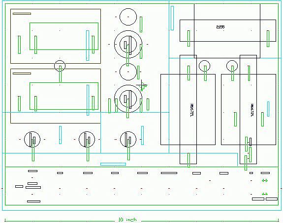
Preamps lower left, effects amp middle, mains wiring lower right; front panel below.
New: 22/7/09
Layout
The position of each of the components above, or the layout, has been given a lot of thought. It didn't just happen or result from where the parts fell.
Layout is always a compromise and there is no such thing as an ideal layout. We want things to be near each other for some reasons, and we want them far apart for other reasons, so a balance has to be found (literally too).
Overall we need to keep the sensitive inputs away from the noisy mains power supply, and from the amps own output. Another important factor is keeping the output transformer(s) away from the hum fields around the power transformer(s). Incidentally this allows us to also physically balance the head for lugging by putting the output tranny down one end, and the power tranny right down the other (e.g. Eminar).
Mind you that didn't stop some commercial builders placing the trannies right next to each other down one end of the chassis. Even if this were not technically dumb it would still defy commonsense - obviously the designer never had to actually pick up one of their own creations.
Flows
Then you have the power and signal flows under the chassis. The heater power is flowing (radially) from the PSU to the valves, while the signal passes serially through the stages, and we don't want these to interact. Nor do we want our input stage to “hear” what is going on the output stage.
We'll look at this more closely below.
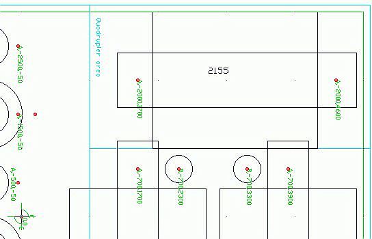
All builds will need the 2155 heater transformer and a suitable pair of trannies for the HT. The drilling allows for three different HT tranny frame sizes.
The holes between the trannies pass the mains primary-side leads (right hole) from the mains termination strip below-chassis, and the secondary side leads (left hole) to heaters and HT rectifier.
PSU layout
With the sensitive inputs on the left of the front panel the Power Supply Unit is hunkered down more-or-less in the opposite corner of the chassis.
The mains cones in there and runs across the far side to the mains switch on the opposite end of the front panel. Some bulders even resort to putting the mains switch on the backpanel next to the power entry point.
The transformers are oriented so that their mains connections are as far as possible protected within the group. The mains coming up and the secondaries going down pass through different holes in the chassis to reduce coupling.
The High Tension multiplier circuit resides inside, below the heater transformer. This is comfortably close to the major load in the amplifier, the output stage.
Typical HT distribution practice was to fit all the HT droppers and their associated bypass electrolytics around the power supply, then run HT feeds from these to various stages.
This results in large loops, often inter-connected, carrying the AC bypass currents for each stage being fed. This does not bode well for a quiet and stable amp.
The right place for a stage bypass cap is at the stage itself, where its ends amount to a local single-point earthing and HT supply for the stage. These are wired back to the single earthing point, and the junction of the HT droppers for supply, but now there are no AC currents in the HT wiring.
Heater power is brought down from the transformer on heavy wired to a distribution point, then in three radial runs, a) for the output pair, b) for the phase-splitter and on to the preamps, and c) for the tremolo stage.
How to wire heaters correctly.
All the action here is underchassis, insulated mains screw terminations for mains lead, power switch, and power tranny primaries.
Mains area layout
The mains lead, the mains switch, fuse, and all the trannies inputs have to be terminated, and this is done using an insulated barrier-strip of screw terminals as detailed here.
This mains wiring is confined to the end of the chassis and the area below the two HT trannies. It is arranged so that no other wiring mixes with, or comes near, it.
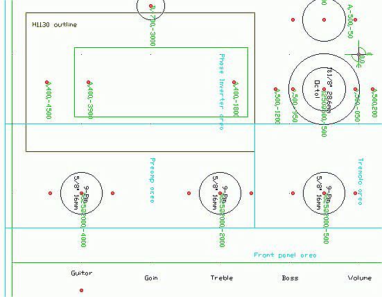
Two 9-pin sockets with optional shields. Four 12AX7 sections for preamp, EQ, line out, etc.
The Fx valve position (middle) is notionally for a tremolo oscillator/modulator, but naturally can be used for a third pair of amplifier sections, such as an output driver stage. Or a triode/pentode could go here as reverb drive and recovery.
Preamp layout
The preamp gain is arranged to start next to the input socket(s) on the left-front, and flow across the frontpanel controls from left to centre.
There is a convention that noise accumulates faster than signal, thus we want sufficient gain in the first stage to quickly lift the signal level to the point where amplifier noise becomes a tiny proportion. An extreme example of this is using an EF86 pentode front-ends to lift ribbon mike and tape head signals out of the noise.
None the less, the entire preamp up to the master volume control is considered a sensitive circuit where significant signal runs should be screened. Where screened cable is used the screen should be connected only at the receiving end earth point.
The first valve position provides the initial gain stage and the post tonestack gain. This means the signal must run across the front panel as far as the gain control, then return to the first valve, creating the potential for unwanted feedback coupling. Often this return is run in screened cable (as above).
Moreover, if the second valve position is used for the phase-splitter it is fairly close to the back of the tonestack. In a build without tremolo it would be better to use this third valve position for the phase-splitter stage. Otherwise the PI wiring should be dressed away from the tonestack wiring.
From a signal point-of-view the tremolo stage and associated wiring are non-critical.
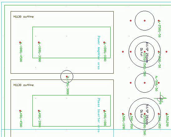
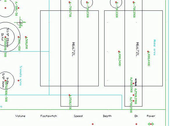
Four output valve positions, allowing up to 4x 7-pin, 4x 9-pin, or 2x Octal output valves. The two miniature quad arrangements allow either a single push-pull quad channel, or two output stages, either in cascade such as the PM-103, VASE Split Sound, or Goldentone 9-60 amps, or full stereo either for stage or home/studio use.
Up to two output transformers can be fitted, and in the case of higher-power single channel amps these will be series/paralleled for power handling and required impedance matching.
The hole between the output transformer positions pass the transformer wiring through the chassis.
Frontpanel left
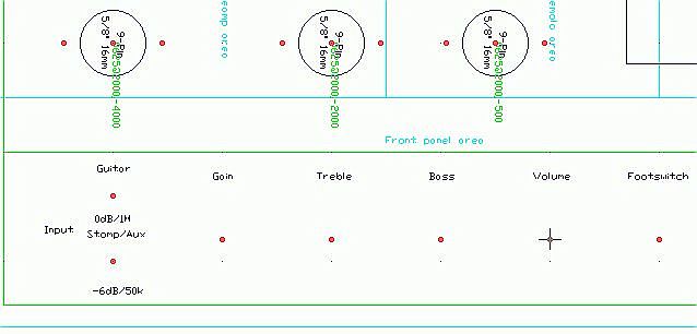
Provision is made for two input sockets, a front-end gain or crunch control, two-way tonestack, master volume (and artwork matching datum). In a minimal build perhaps only one input and only the gain (volume) and treble (tone) would be used.
Frontpanel right
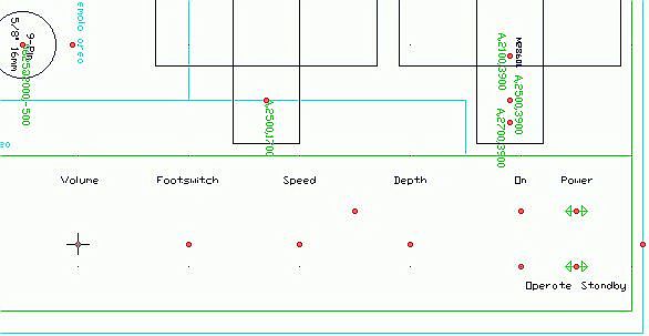
Effects footswitch (both tremolo and reverb can be switched via a single stereo TRS socket).
Next we have tremolo speed and depth controls with a mimic neon in-between, lastly neon pilots for mains and standby, with the switches fitted horizontally beside.