|
http://www.ozvalveamps.org/playmaster.html | Last update:
23:10 7/06/11
<<<OzValveAmps |
From Radio and Hobbies (R&H)/ Radio, Television and Hobbies (RTV&H)/ Electronics Australia (EA) Magazine
Defunct since: ? [later web archives at: siliconchip.com]
Contains:|
Valve:
Old amps, R&H 1954 build, Unit 2, Playmaster 11 & Control Unit 6, PM: 101, 102, 103, 112, 113, 115, 116, 117, 125, 134, 136, 100W KT88 PA, LDR AM vibrato 12AX7, 6X4. Solid state: LDR AM vibrato, Fuzz box, 3 x LDR PM phase vibrato, FET compressor, BJT Hi-Z buffer |
When the now defunct Electronics Australia was known as Radio Television & Hobbies it started publishing its audio designs under the name Playmaster, starting with the Playmaster 101.
New: 8/4/07
EA was brought to a sad end, and even before the final, fatal, “re-package”, “re-vamp” and “re-position in the market” killed it, EA was a very sick duck.
Phillips chronic dys-Information Centre was one particularly long-running bedsore with gross error piled on gross error, month after month; torrents of e-mails about endless bloopers on very basic theory. By the end there was even a website devoted to Phillips-isms.
I come from a generation who gained much of their early electronics from magazines, Practical Wireless, Wireless World, Practical Electronics and Radio Constructor from the UK, and RTV&H here.
They all had some version of “The Serviceman”, and this was generally the most practically instructive part of the magazine. And of all of these, “Hogwash” or “Tiny-Tots” as we affectionately expressed out love-hate relationships towards editor Neville Williams magazine, it had the excellent “Serviceman Who Tells”.
The great-grandpappy of the Phillips-Fiasco Centre was “Let's Buy An Argument” conducted by Williams a bit like a blog. If you look at period mastheads you should see a small incantation after his name - he was actually qualified in the art of electronics. A member of the IEEE, a real Engineer.
I don't know if Williams was a musician but my surmise is that he played a console organ at home.
They had a lot of very significant projects over the years, and the b/w TV set is highly notable, but possibly the grandest of all was the organ, dubbed if I recall the Playmaster Organ, and later a full-size Leslie-style rotating speaker.
So use of the Playmaster name pre-dated this later Playmaster nnn Series.
Naturally these were built not only from the many sets of kits that followed, but also very individually from the “junk box” as means arose.
As they proceeded with Hi-Fi, and stereo preamp 'control units' they eventually produced a design for a small plain combo valve amp, the PM102, a bit like a small Goldentone.
They followed that with the full-featured and more powerful PM103. Even today this still looks like a desirable amp for small gigs and recording.
Over two issues they presented first the Playmaster 116 40 watt guitar amp in June 1967, then the Playmaster 117 60 watt amp as a follow up. “Due to demand” they humphed.
Thing is, there was a crazy numbers war going on and some seriously ball-busting amps appearing at gigs behind people like Thorpie and Lobby, with their Struss, Trent, Eminar, jaw-dropping boxes stuffed with throbbing KT88's, and 40 watts was like Mom's mo-ped. No cred. If you didn't have at least 60 watts you had a small dick. Simple as that. So it was all a bit of a ya-wn until the 60 watt version appeared the following month, then it was hysteria.
There were very similar to each other, and to existing Goldentone and Claybridge designs.
Both the PM-103 and PM-117 had some problems as guitar amp designs, but the PM103 in particular was by far the most practical and useful instrument amp design published up to that time, and I must say, somewhat inspired.
New: 5/3/07
Scans of full articles in Zip files;
Several early Radio and Hobbies amps 1939-1954 (Note 1900kb Zip); basic home-made pickups, novel 6V6 push-pull, and for historical interest only (i.e. don't try this!) an AC/DC amp.
Electronics Australia 1967 guitar speaker systems (800kb Zip).
Electronics Australia 1968 Leslie-type speaker constructional project (800kb Zip).
(credits in zips)
New: 7/6/11
Joe “Ampmangler” has re-created this classic circuit.
Valve stereo amp using a 12AU7 and 4x 6BM8's, a small triode-tetrode, in UltraLinear mode. Circuit.
New: 29/6/07
Frequent contributor Ric from WA has sent a couple of nice pix of a Unit 2, front panel, and inside above-chassis.
New: 2/1/11
Source: ? (please contact AVA)
![]()
This is an extremely detailed, very well researched and presented report on the No11 and No6, a home-built Hi-Fi from the valve pre-stereo era, and its conversion into a Vox AC15-like combo amp.
“CONTROL UNIT No 6. Using 2 x EF86's, high gain unit for any PU switched tone controls. Radio and Hobbies November 1954, page 46. ”
Amplifier - “Radio and Hobbies August 1954, page 70; Radio and Hobbies November 1954.”
The main amplifier is effectively the truly classic Mullard 5-10 while the preamp is already similar to the Vox AC15.
The designs are examined in great depth complete with photographs, characteristic curves, loadlines, original aricle reprints, circuits, and even the new front panel artwork. All it lacks is the authors name - taking well deserved credit for an outstanding work.
Download full PDF report (1.8Megabyte PDF)
Published: Radio, Television & Hobbies, Aug 1962
Stereo main amp chassis (no controls, for use with a preamp/“control unit”) using 2x 6GW8's in ultralinear connection in each channel for around 12 watts for less than 1% THD.

Download scan of RTV&H Playmaster 101 article (.TIF format in ZIP), thanks to Derek Lark.
New: 24/6/09 thanks to Derek LarkBy: John Davidson
Published: October, 1962 to January 1963.
Circuit of basic 12-watt guitar amplifier.
Download whole article series as .TIF scans in Zip (Caution: 3.3MB)
Thanks to: Derek LarkOn Sun, 20 Mar 2005 David Crittle of Retrovox wrote...
The Playmaster 102 combo from RTV&H October 1962 used 6GW8's in push pull, with a 6BE6 for tremolo.
Underchassis pix, left, middle, right. Control panel rear; left, right.
This wasn't the first RTV&H combo guitar amp. The earliest was published in December 1954.
See http://www.retrovox.com.au/construct.html
Published: January 1963
Source: RTV&HAn expanded version of the PM102, including a second output channel (making 12 + 12 watt unit) which could be used for extra power output, reverberation, straight guitar or voice public address.
This type of twin amp arrangement seems to be derived from home console organ practice where extra output stages were used for reverb, rotating-speaker, etc. Other notable amps that used this arrangement were the Goldentones 8/40 and 9/60's, and VASE Split-Sound.
The circuit for the Playmaster 103 is in their black-on-blue period (which followed their traditional white-on-blue). (150kb jpg) Thanks to Joe “Amp Mangler”.
Two pairs of 6GW8's in ultralinear connection (possibly unique in guitar amps), 7199 triode-pentode as preamp and reverb recovery, and the “notoriously” unique 6BE6 pentagrid mixer as pre and tremolo mixer. (Well? There were lots of Radio Shops around in those days - it made good sense then - now we'd use the neon/LDR arrangement from the PM116/7, or even (gasp) solid-state.)
Despite the really quaint and whimsical design the Playmaster 102/3 progression are arguable the best guitar amps the magazine ever produced, and are the inspiration for the AVA100 series.
Transistor 'control unit'. Input selector, preamp and disk EQ.
EA Nov 1966
Stereo power amp
Mid-Fi 15 watt solid state, FET input, active Baxandall controls, single rail, quasi-complementary output.
Update: 15/01/08
Mods
Two mods for both the 116 and 117. The first relates to the orginal power supply. After publication a reader noticed that when the amp was on standby the electrolitic on the centre-tap for the screen supply may be back-biassed.
I haven't investigated this myself since my own 177 uses a different supply arrangement. The obvious fix is to place a standard power diode (e.g. 1amp, 400 volt or better) across the electro with its anode to the positive so it will only conduct if the polarity tries to reverse, thus protecting the electro by “clamping”.
The second is to taste. The original design used a 12AU7 as the first voltage amplifier. This is a rather odd choice since the conventional wisdom is that you want to amplify weak signals up out of the noise a early as possible. It also makes the amp a bit deaf and insensitive.
Evan Lorden has written (11/9/07) reporting that he tried simply changing it for a more normal 12AX7 (which has a lot more gain) and found;
For now I changed the 12AU7a for a 12AX7 and it sounds a lot better, for my tastes. It's certainly doing the job, ...
Another compatable twin-triode that has a gain mid-way between the extremes of the 12AU7 and 12AX7 is the 12AT7.
See also preamp valve FAQ.
Update: 8/4/07
PM116 - published June 1967
These two are together because there is very little difference between them. The only practical way to tell them apart is the output transformer type number - 2842 for Playmaster 117, and 2843 for Playmaster 116.
The infinite variation of homebrew. The top corner strips are leather and there is only one handle for a vertical tote.
By the thickness of the output transformer lamination stack I'd guess that this is a 60 watt 117 (but they were very similar). The two black two-pin sockets were once popular speakers connectors so the '16 R' (ohm) socket may be a retrofit.
Source: Music Swop Shop
Circuit
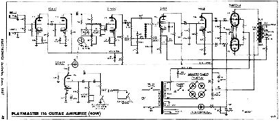
116 (40W) - Click for full size 150k jpg.
back to black-on-white
New 8/4/07
View PM117 (60W) circuit, (93kb gif) thanks to Tim Garbutt
PM116-7 errata EA Aug 1967 thanks to Danny.It was intended to have only a single input, but several tone shaping network options were provided for the user to select. The kits tend to strictly follow the circuits, so you may find three sockets, 'treble', 'flat' and 'bass'.
Two gentle 12AU7 stages follow, and drive the Light Dependent Resistor (LDR) vibrato modulator.
One half of a 12AX7 is used as a phase-shift vibrato oscillator to series modulate a small neon bulb (e.g. NE-2), and the other half as vibrato recovery amp.
This drives a passive-Baxandall 2-way tone control.
The voltage amp and feedback summer consist of the pentode half of a 6BL8 driving the triode section as a split load phase inverter.
This drives a pair of fixed-bias 6DQ6-A's. (the 117 should use -B's only)
The A+R output transformers both provided 3.5, 8, and 15 ohm outputs. There is also a treble boost switch operating on the feedback loop.
Power supply is a solid state full-wave bridge with the screen supply taken from a center-tap. Fixed bias is provided by a 30VAC winding. Resistive filtering.
116 specs
40 watts RMS
THD @ 40W = 0.8%
Sensitivity: 15mV for 40W @ 500Hz
Load: 3.75, 7.5, 15 ohms
O/p trans: A+R OT2748 3k4 55W $16
Power trans: 135-0-135 @ 150mA

117 specs
60 watts RMS
THD @ 60W = 2%, @ 55W = 1%
Sensitivity: 20mV for 60W @ 500Hz
Load: 3.75, 7.5, 15 ohms
O/p trans: A+R OT2842 2k6 55W $14
Power trans: 140-0-140 @ 200mA
Click image for full 10kb gif.For the full story you can read the orginal RTV+H PM116 article text.
New: 2/7/06
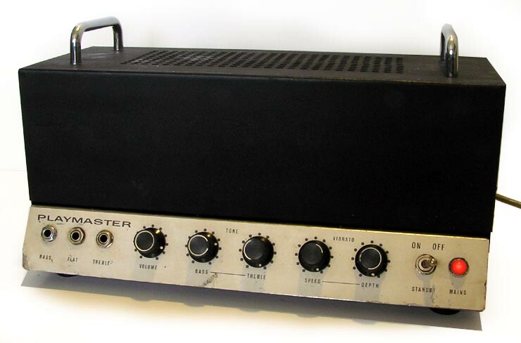

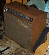
Neil's rave;Source: Neil Rote, Grouse GuitarsGoldentone, Moody, Rex, Electravox, Flame, Vase...early Australian amps are amazing. Previously vastly undervalued (our typical cultural cringe?), vintage Aussie valve amps are now becoming increasingly sought after, for their tone, quality of build (this amp, like most of the era, is hand-built with point-to-point wiring now only found on the most expensive boutique amps) and character. This all adds up to collectability and good investment potential.
Back in the '60s many hi-fi and music enthusiasts built their own amps. The very popular magazine “Electronics Australia” was a must-buy for anyone serious about sound, and they featured projects that could be built by the enthusiast. Commercial versions of these amps were also always available [*], and these were the “Playmaster” amplifiers. This amplifier was described in the June, 1967 edition of Electronics Australia, and a photocopy of the article with all the specs and build specifications comes with this classic amp.
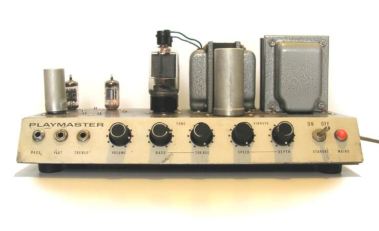
This 40-watt amp is interesting as it shows where Goldentone got their circuit from![*] The amplifier uses two 6DQ6A output valves operating in Class AB1 operation, giving a healthy 40 watts RMS. (Goldentone used to call their amps 60-watters, something that the article in Electronics Australia mentions with some derision!)[*]. These valves have similar plate characteristics to the EL34 and 6CA7, but were very common back in the '60s in TV receivers, where they were used as the horizontal deflection power valve. These valves have the plate connection at the top of the valve, rather than a bottom pin, allowing better isolation of the plate leads (which feed straight into the output transformer in push-pull configuration) from the sensitive low-voltage input stages of the amp.
The phase splitter valve used is a 6BL8, another valve commonly used in TV receivers at the time.
Preamp valves are the usual 12AX7 type.
This amp sounds incredibly nice. It's been fully rebuilt and reconditioned by an experienced tech, and is ready to give years of service to the tone-conscious guitarist. Truly a match for any 'boutique' amp, but a genuine hard-wired article from the '60s, not a modern clone.
$695AUD plus shipping costs.
* just a couple of minor corrections - The power supply was slightly radical, but Goldentone was where EA swiped their basic amp circuit from, not the other way around. Goldentone, Maton and Claybridge 6DQ6 amps very like the PM 116 and 117 long pre-dated this article. EA were dismissive of the power ratings race of the time but their “60 watt” PM117 is virtually identical to 60 watt Goldentones.
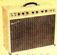
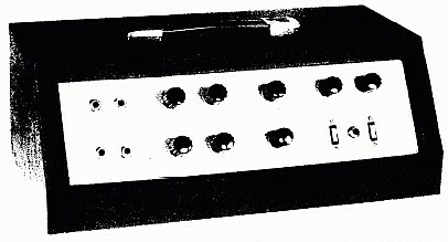
These were never built commercially but this is an example of one of the many kit forms that were available - the front panel is the givaway. This is fully optioned with all three input tone shaping networks, treble boost pull switch on the treble control, and the tremolo switch on the depth control.
Scan of the orginal Electronics Australia Playmaster 125 article (Note 2400kb Zip) April 1969
[8/4/07] 2-point-4 gigs? ... Tell 'im 'es dreaming.
In July 1969 Anthony Leo wrote the article for the Electronics Australia PM125 Guitar Amp. He opened by mentioning the previous PM116 (above) in July '67, and the runaway popularity of the 60 watt PM117 published the following month (and I've still got mine). Then followed high hopes for this new design, their first solid-state guitar amp.
In fact by this time they had already published some solid-state home stereo amps which seem to have worked well enough.
The first problem on sight was the proposed case and packaging (which kit suppliers still slavishly follow, mistakes and all). It was expensive, impractical, and really naff. Anything put on top, such as drinks, will end up down the front panel. The rocker switches are naff - it's almost impossible to get a really neat finish on exposed cut-outs with home construction.
On paper it looked attractive enough to me (after I overcame my dubiosity about transformer drive) as a young tech-cum-working musician to build a pair into a single chassis.
Aluminium “pan” chassis' were available and formed the basis of many projects, not just guitar amps; and they were easy to case like a Marshall head - no sloping anything.
It was a cheap and ready way to move up from my PM117 60 watt amp to the magical 100 watts (and a bigger dick ;). I had access to a folder at work, and the extended front panel allowed a full range of controls, and two lead pockets behind. The chassis is 3-inches high, making an elegant end-on lug.

I was already using a “stack” of two 2x 12 bins with 12PEG's, was playing both guitar and keys, so a twin-50 design made some sort of sense at the time.
But my initial dubiosity turned out to be correct - this thing was a serious crock. (And I now had two of them.)
I can only wonder at the irony of this amp being published in April ... seems fitting somehow. The only other one I've ever seen looked like it had been rapidly pensioned-off to the chookshed.
Utterly disgusting attempt at a solid state replacement for the Playmaster 116 and 117 guitar amps. How could they go from 95% to only 5% so fast?
The first thing I noticed on-stage was how “gutless” this 100 watt unit was compared to my previous 60 watt PM117 (and soon switched back) - it lacked punch, presence, and reach to the back of the hall (same halls, same speakers).
Many of my engineer friends chose to argue technicalities about decibels rather than try to understand the reality of the observations - there was something else happening here. That took the next 30 years.
PM125 circuit
Here is the circuit for the PM125.
Auto-biassed preamps including 2-way active 12dB Baxandall and vibrato, to a 2N3055 class-A driver, transformer-coupled to the output totempole of 2 x 2N3055's biassed with a clutch of power resistors. I think the idea may have been to get 'valve sound' by using the driver transformer. It didn't.
It's hard to find anything right about this amp. Speaking as an electronics engineering type, this amp strikes me as a prime example of engineers who know nothing about the practicalities of being a gigging musician.
There is one thing that is right - the tremolo circuit. This was the latest version of a long series going back to all-valve units deveoped for home electronic organs that were all the rage through the 60's.
Electronically there is a lot to dislike, but from a guitarists perspective the big disaster was using Baxandall-type tonestacks.
Two channels,
each a self-biased transistor preamp into
active Baxandall two-way tone controls,
deep and bright switches,
one channel with vibrato,
all feeding a transformer-driven output stage.

Claimed spec:
50W rms
55W music power
Dtot
0.8% @ 40W rms
1.8% @ 45W rms
4% @ 50W rms

25mV and 200mV for 50W out @ 500Hz
16 or 8 ohm load
My Twin-50 progression
About the same time I was given a circuit for a transistor output stage designed by Delco (semiconductors) that was simple, effective, and singularly addressed our main paranoia which was blowing up the output pair by a momentary short, something all too common on-stage.
The original used a cute pair of drivers 40409/40410 with an integral heatsink, followed by a couple of NPN 40nnn-series output transistors.
This would turn out to be a very conventional arrangement once known as quasi-complementary where NPN/PNP pairs drive output transistors of the same gender, typically NPN. In the early days this was desirable because robust PNP output transistors were yet to emerge, while the NPN 2N3055 was already well established.
It is quite common to use three series forward-biassed diodes on the complementary drivers to provide the required bias and thermal compensation for Class-AB operation.
But this circuit design had a beautiful twist, series-paired diodes between the half rail and each driver base (just four diodes, backwards across the bias diodes, sorta) - producing two current-limited cells. These limit the current to 9 amps, so all that is required is a 5 amp fuse in the output. In the many years since, these have proved indestructable.
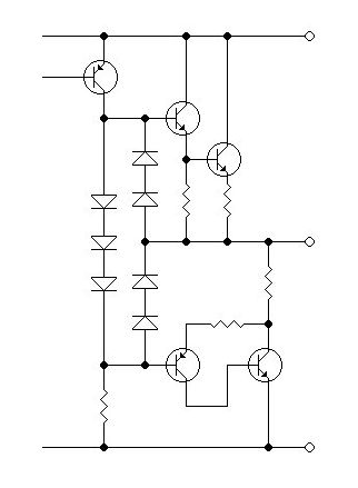
Delco current-limited output stage (some components omitted for clarity) |
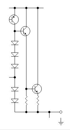
Top cell equiv. circuit when limiting (output shorted) |
Most devices, and certainly early power transistors, don't like high voltage and current at the same time, resulting in high peak powers (exactly what you can get driving a reactive load like a loudspeaker). In these transistors the problem was lateral-current instability causing runaway hot spots that punch-through the dice, also called purple-plague (from the colour of the dice after failure). The allowable times are shown on a SOAR - Safe Operating ARea curve. Many components of all sorts have 'em if you can dig the information out of your supplier.
So it got it's first transplant.
Next the matrix-board-and-wire construction was upgraded to a couple of PCB's. These days I use all BD139/BD140 and 2N3055's for the output. I once conducted a workshop that started with components and blank PBC laminate, and finally played the session out - easy and dependable.
With the change in driver transistors they also moved up onto the main heatsinks without problem. Next two of the three bias diodes followed them for some notable improvements. Un-surprisingly bias stability went from bad to great.
My original-circuit preamp was fitted with “low-noise” BC109C's but still had quite bad noise floor across the audio band, from rumble to hiss.
Moving towards home studio it then grew a LM833-based preamp, and a back middle panel with a number of XLR and TRS connectors, speakers first (I know they aren't authentic, but they are a far superior connector for stage work); pre's out, main's in, that sort of thing.
The Twin-50 is the proverbial 'brilliant axe with three heads and five handles' but continues to move towards being a plain rack amp “box-o-watts” and often gets used for reproduction, foldback, PA, etc, so while it has controls it is mainly used as a slave to a front-end, synths mostly.
Not long ago I found the remains of a genuine kit-form PM125, and apart from the power transformer and the heat sinks, it was a lost cause. Point-to-point hand wiring alone does not a good amplifier make.
Somewhere between the inspired PM102/3 and the PM125 Electronics Australia lost some musical wisdom, someone left, retired or died. The PM117 (Goldentone 60) was the last great guitar amp they would produce, while the PM125 is a Diamond Dot car radio on steroids.
More on the basics of solid state amps, and an introduction to their repair.
Published: Sept, June 1972
20 watt PA
Published: Oct, Dec 1972
Guitar amp[u/d: 7/7/11] (solid state?)
Published: July 1960, download full article 1.2MB ZIP
(also valve PA, EA Feb 1972)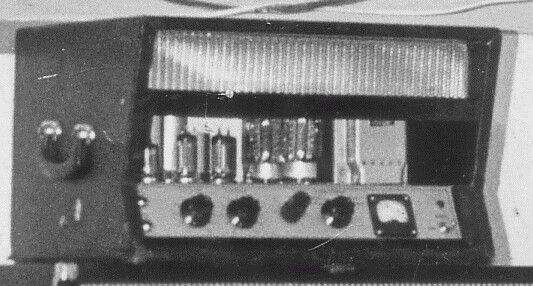
Source: Peter HutchisonI doubt that this was produced as an actual kit so it could turn up looking like anything at all. Addendum: 30/12/10 - Chassis metalwork and apparently some full kits were available, but given its line voltage output (see link) it is unlikely that many were built.
This design was aimed at factory and office PA, race days and surf carnivals where the load was a string of distant speakers running as 'voltage line', so the output transformer deserves special attention.
Inputs are from a microphone, a turntable pickup (line level), or via a 6-pin connector that was common on monophonic 'control units' (input selectors and preamps) of the time.
With its metering, this one's more born out of cinema amps.
The lack of negative feedback is a curious 'feature'.

Click for full size 300k jpg.
[errata: drafting omission - add 0.0033uF cap from anode pin1 to 500k pot to ground]The first stage is an EF86 very low noise pentode as a microphone amplifier. Note the single-point earthing used on this stage.
Connectors are provided for a convential Hi-fi 'control unit', direct record player pickup connection with its own volume to allow manual ducking for voice-over.
Simple top-cut tone control on the anode of the first voltage amplifier stage, half a 6CG7 double-triode.
Note there appears to be no application of global negative feedback, which would normally be applied via the cathode circuit of this stage.
The second 6CG6 triode half is used as a split-load phase inverter.
The phase-splitter is followed by a balanced voltage amplifier around another 6CG7. This post-split gain stage is common with KT88's which were often driven in class-B for maximum power, requiring a 'stiff' grid drive.
These in turn drive a pair of fixed-bias KT88's connected in Ultra-Linear mode to the output transformer. The output transformer has a UL screen tapping on the primary.
Individual adjustments and inbuilt switched metering are available to set each KT88 cathode current, and to balance the drive.
The secondary consists of 4 windings each a nominal 32 ohms. By connecting these all in-phase parallel a load of
Correction: 7/2/07 thanks to Peter Field832 ohms will present the required 4k5 plate-to-plate, to the KT88's.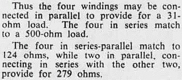
If required, connected in series they will drive (nominal) '100 volt' distribution line.
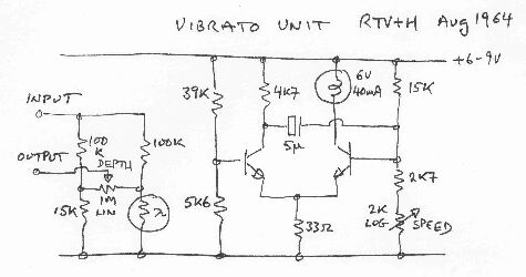
Originally designed as an outboard or add-in this is actually a tremolo unit or amplitude modulator.
I don't have a date for this one but the drawing below is a reversal from a white-on-blue “blueprint” original. For a time the mag published all its circuits in this negative format, possibly to discourage photocopying which was on the horizon, albeit a wet three-part two-step process. They changed to black-on-blue before returning to black-on-white.
One half of the twin triode is used as a phase shift oscillator at the vibrato frequency.
The other half is used as a buffer or gain compensation amplifier for the modulated signal attenuator that follows.
This consists of a modulated path with a light dependant resistor (LDR) in one leg and a fixed resistor in the other.
The depth control allows cross-fading between unmodulated and fully modulated signal.
The optional cathode bypass capacitor sets the stage gain - no cap, low gain; small cap, treble boost; large cap, makeup gain (should be about unity overall).
This arrangement would later be used in the Playmaster 116 & 7 (above).
The signal section is taken from the earlier valve vibrato unit (shown above), but the oscillator is more digital and depends on the lag of the bulb and LDR to soften the modulation.
By the time they got to the PM125 they had advanced to the point where they combined a transistor phase-shift oscillator with the lessons from the compressor, and used a FET as the gain control element rather than the bulb and LDR (which tends to be hissy).
The oscillator is basically an emitter-coupled astable multivibrator or flip-flop. The modulation is therefore effectively more high-low switching rather than a smooth sine variation in loudness (which is important to obtain the subjective pitch-shifting effect).
The network on the left has proven a useful way to modulate the audio path, using any light source you fancy. Keep in mind that it has an insertion loss of roughly 10:1 and requires make-up gain from something like a 12AU7 section.
The 15k resistor can be tweeked to the average resistance of the LDR so that there is no subjective difference in apparent loudness as the depth control is moved from 0 to 10. The natural range of the various LDR's commonly available varies quite a bit.
EA '68
New: 24/11/06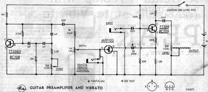
Radio, Television and Hobbies became Electronics Australia and had another slash at it, this time using a sine oscillator (good) and a FET modulator (not so good).
The input impedance presented to to the guitar is nothing impressive either, something less than 80k ohms and would cause severe pickup loading.
It still beats me; from the PM125 in the 60's to the Silicon Chip valve preamp, time and again we see supposedly skilled engineers designing circuits like this for publication without making any reference to what the user wants, the usage conditions, and even the characteristic of the signal source they are proposing to amplify. I can't imagine them trying to design a RIAA-equalised disk pickup preamp like this. They work instruments and play recordings, while we play instruments and work recordings.
At the very least this would need to be preceeded by a high-impedance buffer like this one.
Full article from Electronics Australia (1000kb Zip), Aug 1967 [New: 5/3/07]
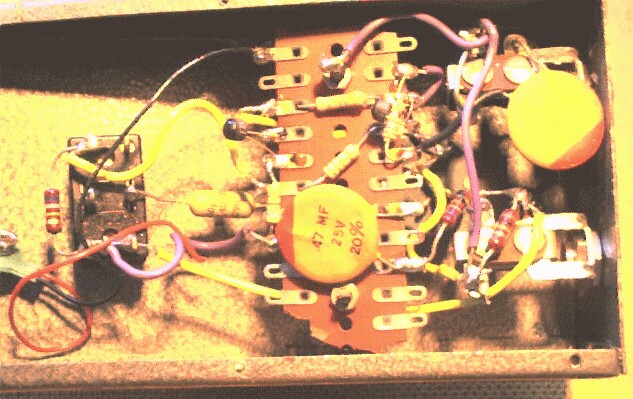
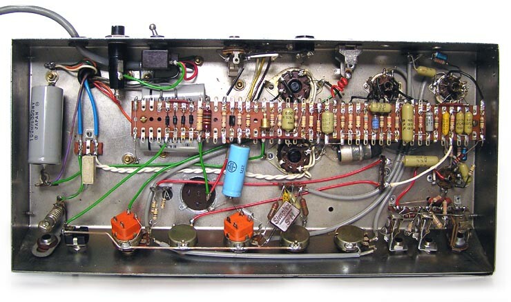
In the sixties it was normal for kits to come with metalwork, as here, with grey “hammertone” painted steel case and front panels.
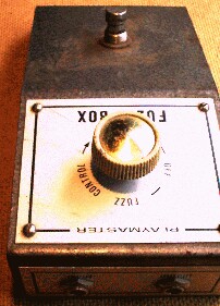
Printed circuits were less common in smaller projects and articles included diagrammes of how to wire the circuit on tagstrip.
Half-watt resistors and these big disk ceramics were the common components of the era.
Power switching used the switch on the fuzz control. Switchpots are difficult to obtain these days, so we'd use a jack socket with an isolated contact for power switching.
I don't know if the white plastic knob came with the kit, but dorky knobs were pretty normal in kits then. It wasn't that there weren't nice knobs around (eg Sato), more I think that the suppliers saw an opportunity to get rid of unfashionable stock.
Thanks to Terry Clear.
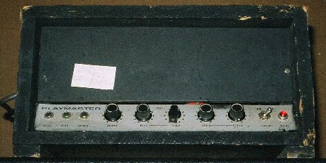
March 1969
Guitar amp “vibrato” is normally simple amplitude modulation of the signal, as above. But influenced by the popularity of console organs at the time EA explored a different form of vibrato using phase shifting.
They had a bit of a thing for console organs and published a design for one that became a bit of a saga. Later they published a design for a “Leslie” speaker and got into trouble for using a brandname lightly.
If anyone has a scan of these real mechanical rotating “Leslie” articles they could send me, I would be most grateful.
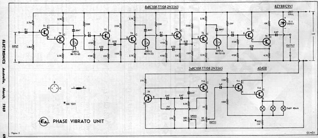
Thanks to Peter G Field.This outboard is a three stage transistor and LDR phase shifter.
Points of note are that this is very similar to many of the “phaser” pedals that followed but makes use of bi-phase drive to each LDR, however the input is not mixed with the phase-shifted output so no frequency selective “picket-fence” cancellation occurs.
You could build this using valves but the noise build-up would be pretty terrible, so FET's and modern low-noise FET-input opamps such as the TL072 could be considered driving a following low-noise audio transistor.
The complex bias arrangement on each transistor following the LDR is called bootstrapping. The signal from the emitter drives the midpoint of the bias network and greatly magnifies the effective value of the input impedance. Not all that common in valve amps, it is often used now in transistor power amps to boost the available voltage at the driver stage.
The oscillator is unusual in that it is a typical phase-shift type but in a direct-coupled amplifier arrangement that uses the minimum of components.
The parallel lamps could perhaps be replaced with LED's in series.
Very useful despite its simplicity. At last RTV+H/EA started to move away from the globe-plus-LDR concept of audio gain control.
A number of these found use in informal recording situations. Of interest to guitarists and particularly bass players, they are fun to play around with, producing clean sustain.
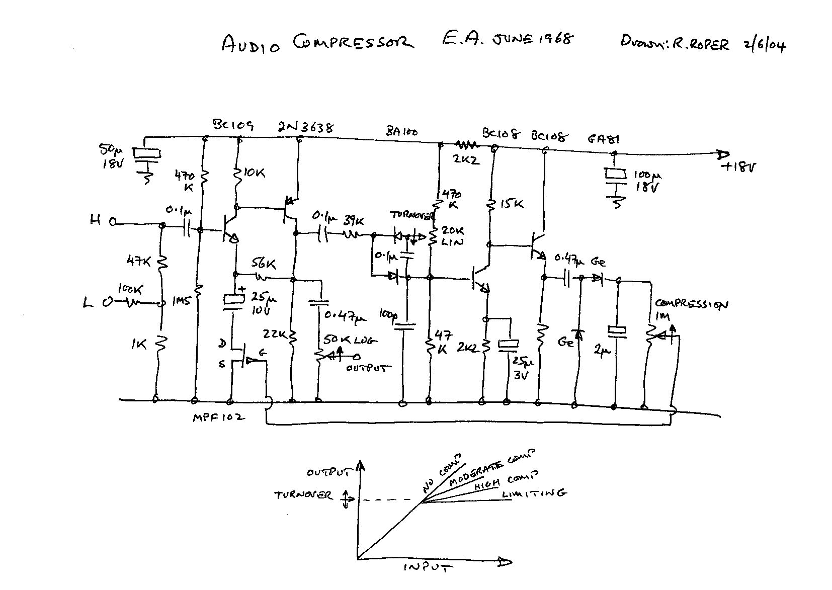
Building this one is a good place to start learning about compressors and their use (and shortcomings); and more generally about electronic gain control.
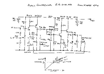
Click for full size 160k jpg.The first two transistors form a direct-coupled amplifier with its gain controlled by a FET in the emitter AC circuit.
The output level is sampled by two diodes which are biassed by the threshold contol to set the level at which compression starts.
This is followed by the control amplifier, a similar arrangement to the first amplifier, but this feeds the signal rectifier consisting of a pair of Germanium diodes.
Germanium diodes are used because their forward conduction threshold is only around 100mV while more normal silicon are between 500 and 700mV.
This control voltage is fed back via the compression control to the gate of the FET which is used as a variable resistance in the local negative feedback on the amplifier.
The choice of FET is probably the most critical part for proper operation and using a FET with less spread than the MPF102/2N3819 will produce more predictable results, particularly if you attempt a stereo version (which I would advise against).
Many accoustic guitars these days come with a pickup that includes a preamp with controls built into the side of the guitar (which offends my esthetics).
But there are still a lot of piezo (accoustic, not magnetic) pickups both fitted and as retro-fits that do not have a preamp.
The problem is seldom level or signal strength as piezos have quite a high output, but the high source impedance of piezo pickups.
Piezos like to work into a load of typically 2M7, while amplifier inputs are typically 1M down to as low as 47k, somewhat better suited to lower impedance magnetics pickups normally found on electric guitars.
The effect of this mismatch is loss of the bass or lower frequencies making the guitar sound thin, shrill, and even producing direct-feedback whistles as you struggle to find a fuller sound.
This circuit is a buffer that presents around 2M7 to the pickup while driving any practical load.
Ideally it should be as close to the pickup as possible, inside the guitar, and it could be phantom-powered. But as a belt-pack preamp to drive the guitar lead and amplifier it would be very practical. It could even include some controls.

The heart of this neat little trick is called 'bootstrapping' (as in lifting yourself up by your own ... ), and is found in the odd biassing arrangement of the first transistor.
To the normal bias divider of 470k and 180k to ground is added another 180k to the actual base, and a capacitor from the emitter to the bias point.
In practice the gain from the base to the emitter is very nearly unity, and because of the 8uF coupling capacitor the bias point is driven by the emitter with a signal only slightly less than the input.
Because the signal voltage across the 180k base resistor is then balanced out, it is 'bootstrapped' to appear to the signal as if the 180k is a much larger value.
The second stage is a simple emitter follower to drive the guitar cable without any fear of treble losses due to its stray capacitance. It also reduces the susceptability of the cable to outside electrical noise pickup by lowering its drive impedance.
Should work okay on 'musicians standard' 9V, perhaps with a bit of bias tweaking.
|
|