http://www.ozvalveamps.org/pickups.html | 25/2/06 | Last update:
19:44 08/09/07
<<<OzValveAmps
|
Pickups
A look at the guitar pickup as a transducer and signal source.
Contains:
This discussion concerns passive pickups only and does not directly apply to active pickups - ones with a battery in the guitar.
A reminder; guitar notes range from 87Hz for an open low E string to 660Hz for a E at the twelfth fret on the high E string. We can approximate that to the frequency decade 80Hz to 800Hz. (see table of note frequencies)
Magnetic
There are many variations, but the basic magnetic guitar pickup consists of a magnet with one of its poles facing the strings, with a coil of wire wrapped around it.
This winding generally has very many turns, thousands, so it has significant inductance, resistance, and self capacitance. Designers play around with these by changing the number of turns, thickness of the wire, and its insulation.
They also play around with the strength and shape of the magnet and different coil winding arrangements, but these are only ways of attaining the combination of factors desired and don't alter the basic picture.
It turns out that you can do some fairly radical re-design, playing around and customisation without even touching the pickup because they are quite sensitive to the load connected across them. This load consists of the volume and tone controls, guitar cable, and input of the amp or stomp box.
Signal induction
The guitar strings are made of magnetic material and so tend to concentrate the lines of magnetic flux in their area because they represent a path of much lesser magnetic resistance than the air, so they tend to each “capture” some of the lines of flux.
When a string moves some of these “captured” lines of flux move with it, and thus also move within the coil. This movement of flux cutting the turns of the coil induces a voltage in them, which we are calling Vint. This is the internal voltage which is an ideal representation of the string movement, but first it has to escape from the real-world imperfections of the pickup itself.
As an aside; the closer you move the pickup to the strings the more flux flows in, or couples with, the strings and the more voltage is produced by a given string movement. However the strings also suffer magnetic drag or damping, causing the oscillations to die away sooner. So you can trade raw output for string sustain by pickup height adjustment.
Harmonics
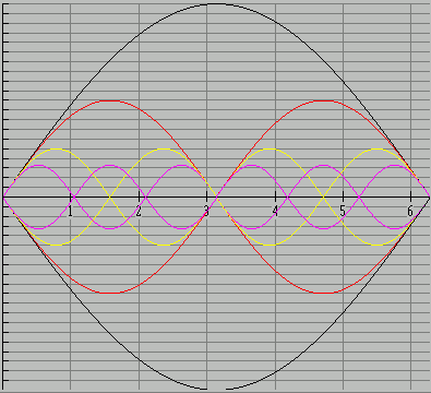
[add: 04/09/07] As well as height, there is the distance of the pickup from the bridge. When a string is struck it is shocked and thus vibrates not only at its fundamental frequency, but at various overtones such as the 2nd, 3rd and higher harmonics.
For each of these overtones there will be one or more nodes, or points where the string does not move for that frequency wave. Where those overtone nodes happen to occur over the pickup there is no movement for the pickup to detect, so these overtones, while present in the string, are lost in the electrical output. This suggests why the “front” or fretboard pickup sounds duller, while the pickup nearer the bridge, often called the “lead” or “back” pickup, is brighter.
|
This diagramme shows some of the oscillatory modes that may be present on a struck string, fundamental (black), 2nd harmonic (red), 4th (yellow), and 6th (violet).
Notice that a pickup placed at “6” will sense all these harmonics and so they will be well represented in the output. But as we move to the left first the violet, and then the yellow, pass through null or nodal points where these is no string movement for that harmonic, and therefore the pickup at these positions won't sense these particular harmonics.
This is a very simplified view of a much more complicated reality, but it should give you an idea of why a pickup may sound quite different in a position that is only slightly different.
|
While we are looking closely, it is also worth noting that the string vibrations are therefore very complex. Initially, when the string is struck by the pick it is stretched out of shape at some arbitary point, then suddenly released. At first the movement is fairly chaotic with many different frequencies of vibration being present, but the string represents a resonant system and this only favors vibations at the fundamental and its harmonics, so energy contained in non-harmonic modes is quickly translated into the harmonic modes.
This indicates why striking damped strings sounds percussive rather than just short duration notes, and why picking near the bridge has a harder, brighter, quality than strumming over the fretboard where fewer high-order harmonics are initially excited.
If we look lengthways along the string we will see that the vibrations occur in different planes - at one moment the vibration will be side to side, at another it will translate, perhaps through a null, to being vertical. Where these vibrations are along the lines of magnetic flux from the pickup the output will be less than when the string is moving across the lines of flux.
Here we look at some typical examples of how a pickup behaves under different conditions so we can get some idea of what effect the following circuitry has on the natural guitar response.
Equivalent circuit
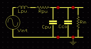
This is the equivalent circuit for a simple magnetic pickup.
Vint represents the signal voltage developed in the coil,
Lpu the inductance of the pickup,
Rpu its resistance, and
Cpu its self capacitance.
Cca is the capacitance of the connecting cable, and
Rin is the input resistance of the amplifier (or effects box).
Strictly speaking we are talking about the amplifier input impedance, Zin, but it is typically resistive across the frequency band of interest so I've approximated it here to pure resistance for simplicity. For the moment we will also ignore the effects of the volume and tone controls fitted to most electric guitars.
|
|
Average Pickup
|
70's Strat
|
|
Lpu (H)
|
4.1
|
2.2
|
|
Rpu (k)
|
12
|
6.5
|
|
Cpu (pF)
|
130
|
110
|
The average was derived from a table of 21 pickups by Helmuth Lemme. (ref below)
For the following examples the values for the 70's Fender Stratocaster® were used.
Naked pickup
This is the response of a naked pickup, no volume or tone controls connected, no lead and no amplifier.
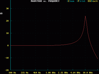
Surprised by the 25dB resonant peak? That's about eight times the midband level! Expecting it to be flat perhaps? Notice that the response above the resonance drops like a stone.
|
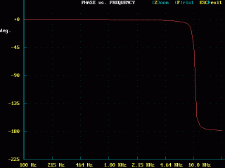
The phase is shown here so you can see that there is a rapid rotation at resonance. This happens in all cases to some extent, but this is not our interest so we'll ignore phase from here on.
|
Leads
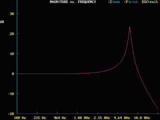
True, at 10kHz this resonance may only be of interest to bats (assuming of course that your speakers can even reproduce it), but let's see what happens if we simply plug a selection of guitar leads with increasing capacitance into the guitar; nothing else, just the lead. Cable capacitance increases with length, and is generally higher in thinner cables.
100pF (~8kHz)
|
200pF (~6kHz)
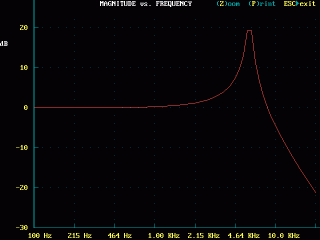
|
500pF (~4kHz)
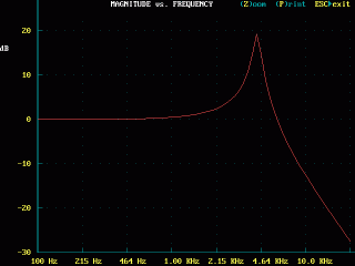
|
1000pF (note changed dB scale, ~3kHz)
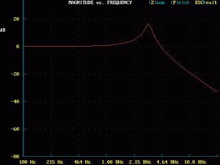
|
So cable capacitance brings the resonant peak down quite a lot in frequency, from about 10kHz to around 3kHz in this case, where it would be having a noticable boost effect on string harmonics. It also causes the ultimate very rapid roll-off above resonance to move well down. While the amplitude of the peak does fall somewhat the main effect of capacitance is to lower the pickup resonant frequency.
Try this: Collect all your guitar leads together, select the bridge pickup, set the guitar volume to maximum and tone to full treble, then try each into your amp and see if you can hear any difference between them.
Input
The input resistance of the amp (or stomp box) the pickup is connected to will also have an effect on pickup reponse.
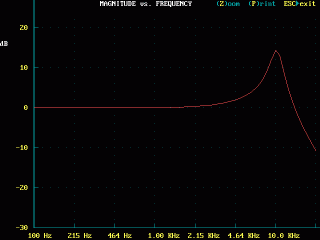
1 Megohm input, typical of many valve amps (+15dB)
|
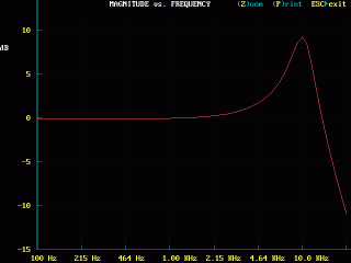
470k ohms (scale change, +10dB)
|
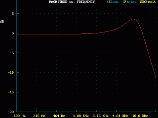
220k ohm (+4dB)
|
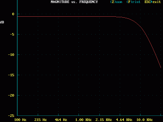
100k ohms, seen on at least one Strauss (-3dB)
|
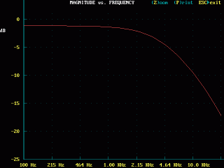
47k ohms, as once used by Elektor in a transistor guitar amp design (-6dB)
|
|
Notice that the input resistance has no effect on the frequency of the resonance which remains around 10kHz, but it causes the amplitude of the peak to flatten right down until it becomes just a roll-off.
Try this: Find out what the input resistance is of the various amps and pedals you plug your guitar into, and you may find some relationship between resistance and how they sound.
“Hum-bucking”
[add: 08/09/07] The humbucking pickup is actually two pickups combined, and works on the same principle as the noise cancelling microphone.
The pickup is sensitive to any variations on the magnetic field and these can come from the desired variations of the strings, called “near-field”, and from undesired sources such as nearby mains transformers in on-stage amplifiers and the like, called “far-field”.
Rather than the simple bar magnet in a basic pickup, the humbucker has a metal pole for each string and the main pickup coil is in fact a series of coils wrapped around each pole. This is intended to pick up the near-field variations.
A second, or humbucking coil is wound around the entire pickup and this is intended to sense the far-field. Natually both coils sense both near and far-fields, but in different proportions, so when the output of the humbucking coil is subtracted from the main coil the effect is to cancel the far field. This is done by simply connecting the coils so that their outputs are in opposition, and what remains is (mostly) the desired string signals.
The term “buck” comes from transformer practice where windings can be connected in buck (subtracting or opposing) or boost (adding or assisting).
Piezo or “Crystal” pickups
The piezo pickup is mainly found on acoustic guitars. It consists of a ceramic element that generates a voltage when it is stressed, called the piezo-electric effect. Since the force-electricity relationship works both ways an element from a piezo tweeter or sounder (e.g. reversing alarm) can also be used as a pickup.
These come in even more physical forms than magnetic pickups. Common forms include a box to be clamped, gaffer-taped, or Blu-Tac®'ed to the guitar soundboard; one or two little blocks intended to be glued to the soundboard inside the body; or a narrow wafer fitted under the bridge in the saddle slot.
The following applies to all passive piezos, whatever the style, typically retrofits to a purely acoustic guitar, but it doesn't apply to guitars built with a battery and a control box cut into the body.
Equivalent circuit
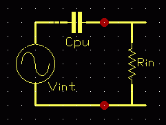
The equivalent circuit of the piezo pickup is very simple indeed, just a signal voltage and a capacitance. That doesn't look like there should be any problem, however the capacitance turns out to be quite a low value.
In this case Vint can be quite high, 100mV to a volt, or more if knocked.
Cpu is also fairly low for an audio coupling capacitor, ranging from perhaps a few hundred pF for a small underbridge to several thousand pF for a large clamp-on.
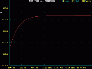
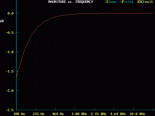
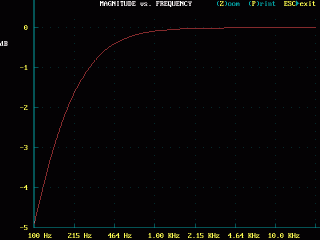
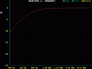
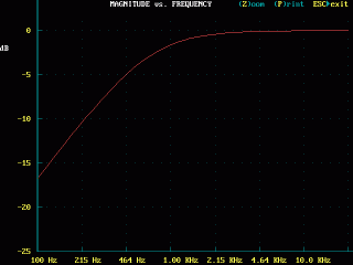
These response graphs assume a self capacitance of 500pF, and show the response for falling values of Rin (note changes of dB scale).
4M7 load
|
2M2 load, about -3 dB on the lowest note
|
1M load, about -6dB or half on the lowest note
|
470k load, about -12db or a quarter
|
So we can see that even the typical 1 Meg input resistance of a valve amp is barely sufficient to prevent loss of bottom end of the guitar. Smaller piezo pickups with less capacitance are even worse.
I didn't include the cable capacitance in this consideration for two reasons, firstly being capacitive it acts with the piezo capacitance to produce a simple frequency-insensitive divider, and because it is typically less than the piezo capacitance and the element has such a high output anyway, we can safely ignore this.
But if we deliberately add a lot of capacitance across the pickup, what happens?
If we assume as above that the pickup has a capacitance of 500pF, then connecting a capacitor of say 10 times that value, 5000pF will cut the signal to about one-tenth (one eleventh actually) or a bit more than -20dB compared to the unloaded output. One volt peak from the pickup becomes about 100mV peak at the amplifier which is similar to the output of a magnetic pickup anyway, so this shouldn't be a problem.
But two capacitors in series like this acts somewhat like a transformer which results in a better match to the amplifier input resistance, hence less low frequency roll-off.
The overall output is well down but now the roll-off in the bass, even with the previously abominable 470k load, is less than -1dB over the range of interest. With higher and more reasonable input resistances such as the typical 1M amp input resistance the curve is almost flat down to 100Hz.
The Active pickup
One answer for both types of pickup is to use a preamplifier at, or very near, the pickup. When such a preamp is fitted inside the guitar it is then called an active pickup, and requires power in some form, normally a 9 volt battery.
“Preamp” is a bit misleading since we don't actually want any voltage amplification, rather we want to present a very high resistance to the pickup while driving a high capacitance cable.
The normal answer is a unity-gain buffer such as a cathode-, emitter-, or source-, follower.
Of these the obvious choice is the FET, but if you want to try and wangle a 12AX7 and power supply inside your Strat somehow, that's fine by me.
It should be mentioned that with both types of pickup any passive controls connected directly to it, such as on the guitar scratchplate, need to be as a high a resistance and possible. By including a buffer in the guitar it is then possible to apply the volume and any tone controls required after it, allowing more common lower resistance parts to be used.
In the case of a piezo once a suitable value of capacitor has been found it can simply be fitted and forgotten.
In the case of the magnetic pickup it would be nice to retain the ability to tune the peak up and down, and to flatten as required. By changing the tone control for a multi-way rotary switch it is possible to have a selection of resonating caps that can be switched across the pickup ahead of the buffer.
It is even possible to mark the switch positions with frequencies if desired because the buffer will isolate the pickup from cable and amp variables thus allowing consistant results.
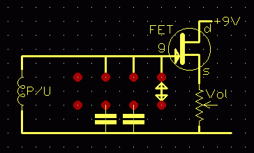
Here is the general (untested) idea.
The switch selects from a range of capacitors chosen by experiment to resonate the pickup at various musically useful points.
Just about any FET such as the MPF102/2N3819 should do.
If you can find an output socket with an isolated switch contact that fits the guitar this can be used to switch the battery when the lead is unplugged. But with most common values of volume pot (250k to 1M) the battery should last close to its shelf life anyway if left connected.
Here is a circuit for a high input impedance buffer using bipolar transistors, from Miniwatt Digest.
For a more detail about pickups visit Helmuth E. W. Lemme's “The Secrets of Electric Guitar Pickups” site.
PC-ECAP
All the plots above were done using a DOS programme PC-ECAP v3.02
“PC-ECAP is an easy to use AC circuit analysis program which analyzes circuits consisting of resistors, capacitors, inductors, transformers, transmission lines, transistors (both bipolar and FET's), operational amplifiers and transconductance amplifiers.
”
Source: http://www.epanorama.net/links/software.html
Download: ecap302.zip
Shareware $69, demo has growing delay nag screen at start, but still very useful.
An understanding of AC equivalent circuits is required to create a nodelist from a schematic or circuit diagramme.

