http://www.ozvalveamps.org/solidstateamprepair.html | Created: 21/06/09 | Last update:
17:56 30/12/10
<<< OzValveAmps
|
Solid-State Amp Repair
“Where are the valves?”
Like mice, solid-state guitar amps are a reality of life that has to be dealt with.
New: 21/06/09
In the case of era guitar amps “solid-state” boils down to ordinary bipolar transistors, and the odd 741 op-amp - FET's and Darlington “super-transistors” had yet to make any impact.
PNP transistors also still tended to be a bit fragile, so the majority of amps are one arrangement; NPN quasi-comp's. Don't Panic - you will still have the mains under the chassis to keep you awake, and transistor amps can be repaired without fireworks as long as you take care of a few things.
Assuming that we are confronted with a solid-state amp on the bench, and all we know about it is that it is “faulty” in some way, how do we go about bringing it back to health?
[Open an annotated underchassis view in a new window of the typical amplifier under discussion so it can be easily switched to as desired]
The first thing to do (after the normal mains lead and plug safety check), is to have a good look and smell. I had a multi-headphone amp in the other day and I could smell burnt resistor before I had the lid off.
With all faulty gear it is possible to seriously compound your troubles simply by powering it up to “see what gives”. The danger is that something very expensive or unobtainable may “give” - such as the power transformer. So before we apply any voltage we have a damn good poke around inside first.
|
These days, the second thing I do is Google the model number, and any transistor types I don't know and grab their datasheets (almost always PDF's). Sometimes this turns up significant information such as a circuit, or how someone solved the same problem previously.
|
I use cleaning the inside of the chassis as an excuse to see in detail what it contains, pick up any clues about what type of circuit it is, and what might be wrong with it. I use a paintbrush and vac, and by the time it's clean I often have found broken wires, burnt components, and have a very good idea what happened in what order, and who else has been inside the chassis. This is what I call reading the chassis, and sometimes they “talk” to me, even saying “Thank God You're Here!” like the Gibson.
Testing Semiconductors
Using your multimeter on its diode/continuity setting (or low ohms) a good transistor looks like two diodes from Base to Emitter and Base to Collector, thus;
On DVM diode test (with red +ve probe on the Base *) there should be roughly 600mV(±100mV) between the Base and Emitter, and Base and Collector, but should appear open when reversed. Collector to Emitter should test open both ways.
Generally a damaged transistor will show a short or only 10's of mV between two connections, or very high or open where there should be a diode.
Cold in-circuit testing can give you a strong clue that a transistor is faulty, but it cannot confirm that a transistor is good because of the surrounding connected components.
When in-circuit tests are doubtful, the only certain way is to isolate the transistor, but be sure to note its orientation for replacement. If it helps physically, we only need to isolate two of the three leads.
Remember that your fingers have resistance.
(* NB: DVM's have the +ve on the red lead, but moving-coil multimeters have the ohms range +ve on the black/common lead)
|
Power supply
In all amps the power supply can be considered to be an intimate part of the power output stage. In the event of an output stage blow-up the power supply diodes must be an early check. It is generally an easy matter to isolate the power supply output (at the supply end so we don't have wires dangling with power on them), and to confirm the supply is producing the correct voltage(s).
NB: as with valve power supply caps, it is not a good idea to discharge power supply caps by shorting them. The same lamp load we use for discharging high-voltage caps will serve equally well here. Just shorting is a bad habit to get into because a really big rack amp can chew the end right off your favorite screwdriver.
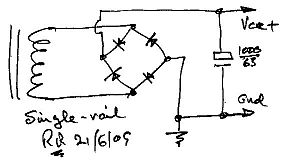
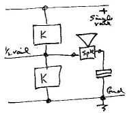
single-rail
Look for ...
- No transformer centre-tap
- A single power supply filtering capacitor
- A big electrolytic cap in series with the output/speaker
Be aware that some Asian manufacturers use black for ground and red for “live”, even if the “live” happens to be the negative supply for a PNP-based amplifier. Do not assume that because a supply wire is coded red it carries a +ve voltage - check.
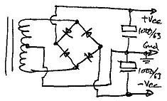
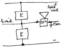
Split-rail or bipolar
This form can be considered as half a bridge with the other half being the output pair, and the speaker load connected between the mid-points.
Look for ...
- A transformer centre tap (normally grounded)
- Two identical filter caps in series
- Output is DC-coupled to the speaker
Electronically it makes no difference to the amplifier if the cap is before or after the loudspeaker. In the event of a fault that upsets the power amp DC condition however, placing the cap between the output stage and the speaker load will prevent DC being impressed on it (no speaker protector with dubious relay contacts, required).
Preamp power
Sometimes you find a specific supply for the preamp, generally when they have used op-amps and want a regulated split supply.
Where we find split supplies (or multiple voltages in organs and the like) we frequently find some form of voltage regulator. In older gear a regulator will be built out of individual components, while in later gear we may find a 723, perhaps with a booster transistor, or the 75vv and 76vv (where vv is the voltage such 12, 15 or 18). The point to remember about these excellent regulators is that the pin connections of the 75vv (+ve) and 76vv (-ve) are different.
The most common method however is to derive the preamp power via a dropper resistor from the main supply, often clamped to 10-15V with zener diode.
Where fitted, this zener has a pretty hard life and can fail short circuit and take the dropper resistor with it.
Generally speaking the solid-state age brought with it an optimalism about how hot components would get in normal service, and the implications for their life and the life of the components around them, particularly electrolytic caps. So many of the faults found in era solid state amps relate to excess heat, and being unable to get rid of it. The Savage is a gross example.
Preamps
There is not really a lot to say electronically about preamp repair since the problems are mainly mechanical, broken sockets and controls, noisy pots, &c.
I have had one case of a preamp producing “scrunching celophane” and “popcorn” noises that was traced to a salt film on the bottom of the transistors, and cured with a good metho scrubbing.
Certainly there are many cases where era solid state preamp performance can now be much improved, particularly with respect to residual noise floor and crossover distortion. It may be worth trying a specific low-noise transistor such as the BC109 in the first transistor position, but generally the best improvement in noise and distortion will be had by moving to a more modern op-amp such as the LM833 or better. I have been down this path with my own PM125 to Twin-50 progression, from self biassed BC109's to LM833's, and for my needs the LM833 is as close to a prefect amplifier as I could wish for. I could fit better, but the residual noise level is already effectively nothing.
These days older op-amps in the signal path such as the 709 and 741 are a bit like having leaky waxed paper caps, and can normally be replaced with TL071 or TL081 to good effect; old duals such as the very common 4558 with TL072, TL082, or LM833; and the slow 324 quad with TL074 or TL084 (the LM324 is however ideal for non-signal-path control service and should not be replaced).
Output stage
I'm concentrating here on problems around the output stage because that is the area where most problems occur, and where repairers strike the greatest trouble. Preamp problems are more often simply broken connectors and the like, and even serious errors are unlikely to result in expensive smoke.
But it is very common to hear stories of output stage “repairs” that promptly ate several new transistors at first switch-on.
This is because the typical solid-state output stage is a fully DC-coupled loop around six (or many more) devices. In many respects it is a bloody big op-amp on steroids, capable of ripping its own arms off. If only one of those devices is faulty there is a very high chance of galloping silicon cancer when power is applied. At best this only leaves you red-of-face and out of pocket, but at worst it can be a disaster. Do no harm - don't make matters worse than they already are.
“You can't service a closed loop” - truism
Well you can, but you need to be very aware that a fault anywhere within the loop will be reflected throughout the whole loop, and that means that DC conditions up-stream from the fault will also go crazy, thus effectively hiding the offending component. Because of the very high open loop gain, opening the DC loop for diagnosis is not a workable proposition with a solid state amp, so we initially have to depend heavily on careful cold tests.
In valve amps we very rarely find DC coupling and only have to cope with AC instability, but DC coupling between stages is very common throughout solid-state amps, both pre and main amps. So any fault that throws off the DC conditions tends to be reflected pretty drastically around the loop.
So if we have fuse-blowing, or find even one dead device, we have to take the greatest care to be sure we have found ALL the faulty devices BEFORE we apply power.
Even then we use either limiting power resistor(s) in the supply, or our trusty load limiting lamp in series with the mains until we are certain all is well for a full voltage test.
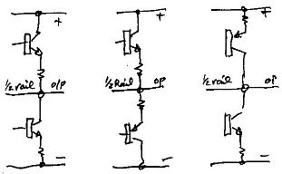
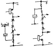
Output arrangements
The output totem pole on the left is the most common era arrangement using two NPN power transistors in a quasi-complimentary NPN arrangement.
The middle arrangment is a fully-complimentary emitter follower, very common in transistor radios, and smaller stereos and guitar amps.
The right hand fully-complimentary collector follower is normally only found in later up-market stereo (and big rack) amps, and is rare in era guitar amps. Power freaks should note that this arrangement provides more power to the load since it is capable of swinging the output to the supply rails (minus the transistor saturation voltage), while the quasi-comp is hard pressed to get within a couple of diode drops.
Output coupling
Single-rail cap coupling (left); split-rail diect coupling (right).
Basic active cells
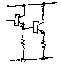
Basic NPN cell (left); basic PNP cell (right)
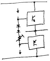
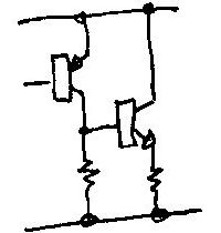
Applying bias
Voltage Amplfier Stage gender
VAS - PNP (left); NPN (right), also bias and bootstrap
Component substitution
After a serious blowup we are often confronted by components that have suffered so much damage they are unreadable, possibly even vaporised. But if you find a badly burnt resistor it is worth measuring its resistance before removal - sometimes it will still measure close to its original resistance and save a lot of bother.
But generally we need to trace the circuit, at least around the burnt component, to determine where it fits in, and that should give a good clue to its value.
Where smaller transistors such as drivers have been destroyed or are unreadable, again we need to trace enough of the circuit to identify the gender and connections, and a BD139 or BD140 works for me.
The emitter resistors of the output pair are often roasted beyond recognition, so how do we find the right value?
Investigations by Doug Self showed that the optimum value for quasi-comp emitter resistors is 0.22 ohms. Again, I have simply used 0.22r/5W ceramic wirewound whenever I have encountered this problem. In this case the hot tests for bias stability are more important; I've yet to have to readjust the bias on such a repair - but you may find the odd one.
Germanium transistors
Worth a mention on vintage gear are germanium transistors. These pre-dated silicon semiconductors and were fairly quickly displaced, but some amps were built using them right up to the power stages - and don't be surprised by driver and output transformers. Germanium transistors really don't like heat and should operate no hotter than warm. But they do have one interesting property, a freedom from second-breakdown or lateral current instability, the ability to survive spikes that would kill most silicon transistors, hence their popularity in magnetically coupled circuits.
The two main differences when testing these devices is that the “diode” cut-in voltage is closer to 100mV than the 5-600mV of silicon, and a good device will appear to be leaky compared to silicon, making it harder to tell a good device from a dud one, generally requiring an out of circuit leakage and gain test.
These days germanium transistors are virtually unobtainium so restoration will mean silicon substitutes and re-biasing.
Some real examples
It is important when looking at these circuits to keep in mind that there are also many hybrids, that any of the output arrangements may be found with any of the driver or input arrangements, and that VAS and input stages may be mirror images flipped upside-down using PNP rather than NPN transistors, as shown above.
This shows the basic theme. Ultra simple single-rail, fully comp emitter follower. Economical and efficient this is typical of cheaper transistor radios, but will have high crossover distortion and limited output power.
Up a step, this 250mW design uses a half-differential input, that is a single transistor setting the half rail voltage between its base bias and its emitter sense. Note that very basic driver bootrapping has been applied via R6.
Note also that because of C3 the loop has 100% feedback at DC, thus unity DC loop gain, and thus hopefully good thermal stability; but the AC loop gain is set by the ratio of R4 and R5;
Av = R4+R5/R4 = 100+2200/100 = x23 or about +27dB.

In the previous examples the output pair was driven by the VAS (Voltage Amplifier Stage), but as power levels go up so do drive requirements, thus in this 4-watt amp we introduce a medium-power driver stage (almost always a complimentary pair, such as the BD139/140, here a BC547/557). We also now have three forward diode drops, so a third diode is added to the bias string to compensate.
At first glance the examples above should all be operating in stavation bias and producing a high degree of crossover distortion. As the power level rises so the output pair warm and their EB voltage drop falls, leading to some forward bias. The emitter resistors prevent this trend getting out of control.
“Bootstrapping” is also added in the form of the 220uF/1k0/2k2 in the VAS collector circuit. This causes the output to drive the midpoint of the 1k0/2k2 more +ve than the supply rail during +ve signal peaks, maintaining drive to the upper driver base - causing the stage to “lift itself up by its bootstraps”.
The similar-looking network on the front end consisting of 220uF/10k/33k is actually additional bias supply filtering to keep supply rail noise out of the input.

Now we get pretty serious with a 100 watt design. Q1 and Q2 form a proper NPN differential input amp, input to one side and both DC and AC NFB to the other. The VAS, Q5, has a constant-current load, Q3, rather than just a bootstrapped resistor, and the thermal compensation is being done by a single forward-biassed transistor, Q4.
This particlular arrangement is problematic in that if the bias setting pot wiper should go open circuit, quite likely with the typical open trimpot, the amp will go into full conduction, top and bottom, and quickly blow itself to hell. A better arrangement is to use a fixed resistor beween base and collector, and place the pot between the base and emitter where going open will de-bias the output.
Safe Operating Area (SOAR) protection is provided by Q6 and 7 which sense (and limit) the output stage currents as the voltage across their respective emitter resistors. As always Murphy Rules and protection of this type can cause mysterious distortion with certain (reactive) loads but not others (resistive); and like all protection circuits are subject to their own failures, acting when they shouldn't and not acting when they should. The output stage is of the fully-complimentary emitter-follower type.
Big example - Collector-follower output (Q1 & 7), current sinks (D5, Q8 & 9), PNP VAS (Q2), fully differential NPN input (Q4 & 5).
The use of the TIP2955/3055 pair brings up another point. There is nothing wrong with TIP or MJE series thermopad transistors, but none of these similar types have the same ratings at the TO-3 package 2N3055. Be aware that the 2N3055 power spec is 115 watts, while the TIP and MJE 2955/3055's are rated at 90 watts.
For every other position, including input, I have found the BD139/140 to serve very well.
New: 12/12/09
An even bigger example of an Acoustic 361, power supply and input stage, output stage.
This amp illustrates the use of paralleled output devices to obtain greater current capacity. An identical device is used as the driver to cope with the increased base drive current requirement, and these are driven by a NPN/PNP pair of pre-drivers. The output is capacitively coupled to the speakers.
Reading the chassis
From inspection of the underchassis photo we are able discover quite a few things about this amp.
Single or split-rail supply?
The single filter cap in the supply, and the use of an output coupling cap, point to a single-rail setup.
Fully comp, or quasi-comp?
The most obvious thing is to look at the type numbers of the output pair. If they are the same then it's a quasi-comp, if different then it's fully complimentary. The Asian 2SCnnnn or Cnnnn series are NPN, while the 2SAnnnn or Annnn are PNP.
We note that the supply +Vsup is connected to one of the output collectors, suggesting that it is NPN. The fact that the order of the leads from the other transistor are the same suggests that it is also NPN.
PNP or NPN VAS?
The physical position of the VAS transistor places it at the lower end of the bias network, suggesting that it is an NPN.
Half or full diff input?
Only one small transistor near the input, so it's a half-diff input.
Cold tests
As outlined above, most of the spadework is done using a diode tester/millivoltmeter or ohmmeter.
Hot tests
First we have to bring the amp up. To prevent blowups due to something we have missed it is important to limit the current available to the output stage.
One method is to insert a power resistor in the supply line (or one in each supply line with a bi-polar supply). I have a couple of 150ohm/10watt resistors I use for this. Alternatively we can use our limiting lamp lead fitted with a 15-25 watt globe in the mains feed (assuming we have already checked and discharged the power supply itself).
Unlike a valve amp, initially we don't want any load, so the speaker is disconnected.
With some voltage applied we are looking for the half-rail biasing to around half the supply voltage. Serious imbalance, or excessive current draw need to be investigated before proceeding.
If all seems well we can remove the resistors, or move up to a 60 watt limiting globe.
Clip the voltmeter across the whole supply and apply power for a second or so. The voltage should rise quickly to the idle value, typically 50-70 volts, and decay slowly when switched off again. A rapid decay suggests too much current is being drawn (excessive bias setting), or possibly a dried out main filter capacitor.
Again any problem must be sorted before proceeding. But if all still seems well then the voltmeter should be connected to the output half-rail, and power can be reapplied while watching carefully for any overheating or thermal runaway. If the half-rail voltage settles close to half the supply then the output stage can be assumed to have healthy DC conditions.
Where a split-rail supply is used we need to check the residual voltage across the output. Generally this should be no greater than about 100mV.
Once we have got to this point the amp is basically going again and we can proceed to signal and quality tests. These include checking that the idle current is reasonable, say around 20-40mA, and particularly that it remains stable as the power stage warms up. Any continuing upward trend of idle current with heating is a particular concern as it can result in thermal runaway and output stage meltdown. Over-compensation on the other hand will result in increased crossover distortion when hot. See the Gibson repair for detail on how to address thermal instabilty.
If you have something to add, a tip or method, pitfalls to avoid, or just your experience of repairing a solid-state amp you would like to share, then please send it in.