http://www.ozvalveamps.org/tonestacks.html | Created: 13/11/06 | Last update:
18:05 04/04/07 (typos)
<<< OzValveAmps
|
Tonestacks
How tone controls work
Contains:
- All Pass
- High Pass
- Low Pass
- Response estimation
- - Rules of Thumb
- - Drive and Load
- - Source impedance
- - Load impedance
- Application
- Big-Muff
- The Volkoff (James) control
- The Baxandall control
- The Bench Control
- Duncan's Tone Stack Calculator
|
The term “tonestack” is unique to guitar amps. Certainly most amplifiers are fitted with some sort of tone control, beit a single knob top-cut or the more normal bass and treble controls.
While the Hi-Fi world has heated and rather vacant disputes about fitting any tone controls at all, guitarists have a fetish for them and it's not uncommon to find guitar amps with quite a number of controls and switches that are capable of totally mangling the frequency response of the amplifier. This is about as far as you can get from Hi-Fi and still be talking amplifiers.
Generally these get called “tone controls” and “EQ” for equalisation (of frequency response), but only guitarists call them “tonestacks”, which is just as well since in a guitar amp they do anything but equalise response. Tone shaping is very much part of the creative process of making music and it often takes quite radical forms.
One thing all tone controls have in common is that they are frequency-selective circuits, that is they pass some frequencies better than others.
The key to this is the fundamental behavior of the capacitor. In effect a capacitor presents a different “resistance” to different frequencies. In that sense it is a frequency-selective. This resistance is called reactance, symbol X, it's unit Ohms because it is an effective resistance.
All Pass
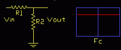
If two resistors are placed in series (end-to-end) they form a voltage divider.
Simple voltage divider or
attenuator
This voltage divider, or attenuator as it is called in some applications, reduces the input voltage and is the basis of the volume control.
Its output, Vout, is a fraction of the input, Vin, and is found by the proportion R2 is of the whole, R1+R2, thus;
Vout/Vin = R2 / (R1+R2)
or, rearrange for output as a function of input...
Vout = Vin ( R2 / (R1+R2) )
The little graph to the right is called a Bode Plot and shows the circuit response against frequency. The response is vertical and generally in dB (decibels), while the frequency is horizontal and generally on a log scale.
Here there is no frequency-selective component, so the response is flat, as shown by the red line. (Fc has no meaning in this case and is explained below)
Low Pass
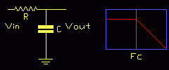
If either of the resistances is replaced with a capacitor we get a frequency-dependent divider or volume control.
As the plot shows, the response is flat until we get to a corner frequency Fc, after which the response falls with frequency. This is the basis of the most basic form of tone control, the top-cut.
Fc is the corner frequency for the network and is derived via the formula that relates the reactance of the capacitor to frequency;
XC = 1/(2 π f C)
You may see the following expressed ω=1/CR, but since ω (angular frequency, omega) is 2πf then;
Fc = 1/(2 π C R)
High Pass
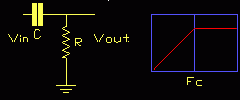
Naturally the opposite of a low-pass network is a high-pass network, and we get this by swopping the resistor and capacitor around.
Notice that this is identical to the typical interstage coupling network, and will have a low frequency cutoff given by the values of the coupling capacitor and grid leak on the following stage. If your amp has a coupling capacitor of 0.01uF with a following grid resistance of 100k and you play bass, you have a problem. Similar considerations apply to the cathode resistor and its bypass capacitor.
Response estimation
Thankfully there are graphical methods of working out frequency response that save a lot of calculation once you know the corner frequency Fc.
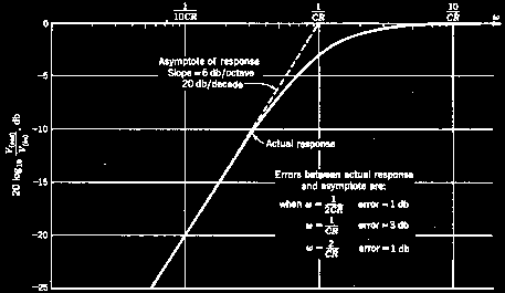
As it happens, we can plot frequency response as straight lines around Fc without having to compute the actual curves. The straight line approximations are close enough to the real response for us to ignore the errors from the exact result as normally insignificant in practice.
Rules of Thumb
For each CR element the ultimate response slope is 6dB per octave, or 20dB per decade.
So for cut or boost circuits the reponse falls (or rises) by half (or doubles) for every octave from Fc.
This is exactly the same as 20dB per decade or one tenth (or ten times) change in response per decade in frequency change, e.g. from 100Hz to 1000Hz.
The actual errors of this straight-line approximation are 3dB at Fc and only 1dB at twice and half Fc.
This is generally true, beit for bass or treble, boost or cut.
The corner frequency Fc can also be defined as the frequency where the reactance of the capacitor is equal to the resistance (see above).
Drive and Load
Another quite important factor with all filter circuits is that they are driven from a source impedance that is low enough, and output into a load impedance that is high enough.
Generally a filter or tonestack needs to be fed from a source impedance that is ten times lower than the impedance of the network, and be presented with a load impedance at its output that is no less than ten times the network impedance (at Fc).
Source impedance
In guitar amps the tonestacks are typically driven from the anode of a preamp stage, and the output impedance can be approximated to be half the value of the anode load resistor.
A variant is to drive the tonestack from a cathode follower. In this case we can normally approximate the drive impedance to an ideal zero ohms.
Load impedance
On the output side the tonestack is often directly connected to the grid of the next stage, and we can safely approximate this to an ideal open circuit.
A major variant is to follow the tonestack directly with the volume control, so the network is loaded with the value of this pot, traditionally one megohm. For most tonestacks this is not an insignificant load and needs to be accounted for.
Failing to align the network impedance between the available source and load impedances will result in a control that does not work as intended.
Application
Of course the above has a much wider application than just tonestacks and turns up all over the amplifier in power supply decoupling, cathode resistors and bypasses, and interstage coupling. This allows you to answer questions like “what value coupling caps are sufficient for a 5-string bass?”
Big-Muff
Source:
Duncan's Tone Stack Calculator
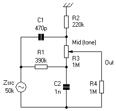
Specifically designed for use with electric guitar, this is perhaps the simplest combination of the low-pass and high-pass networks shown above.
The low-pass network (lower) consists of R1C2, and the high pass network (upper) C1R2.
These are connected to opposite ends of a single pot allowing any mix between the two signal paths.
The low pass is tuned to;
Fc = 1/(2 π 390e3 1000e3-12) = 408Hz
Note that this is the frequency where the reactance, Xc, of C2 equals the value of R1.
The high pass is tuned to;
Fc = 1/(2 π 220e3 470e-12) = 1539Hz
Note again that this is the frequency where the reactance, Xc, of C1 now equals the value of R2.
The high-pass is tuned about 1000Hz above the low-pass, and with the control set at the mid-point this produces a dip in the middle of the overall response that guitarists call a “mid-band scoop” and many find favorable.
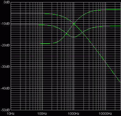
Middle and control extremes
You can see that we can tune these two networks independently of each other, so we can move them further apart and produce a deeper scoop, or closer together thus reducing or even eliminating it.
Similarly we can scale both networks up or down together to move the mid-frequency of the scoop as we desire.
The James/Volkoff control
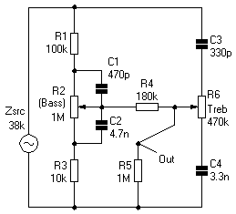
This is sometimes also called the “passive Baxandall” because of its superficial similarity to the later Baxandall design. Published by E.J.James in Wireless World (now Electronics World) in Febuary 1949, but apparently designed earlier in July 1935 by Michael Volkoff.
Source:
Duncan's Tone Stack Calculator
The default TSC values shown above give a more reasonable set of responses than the values used in the original article. The function of R4 is to isolate the treble control from the bass control network.
This network produces a characteristic that “hinges” around the corner frequency which is typically 1kHz in Hi-Fi application. As the controls are varied so the slope of the response is changed, but the origin or hinge point remains fixed. So the action is spread across the entire spectrum of the control and thus fairly gentle.
The Baxandall control
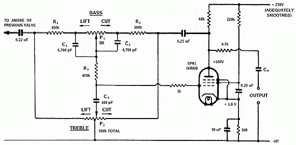
This arrangement was first described by Peter J. Baxadall BSc again in Wireless World in October 1952.
Source:
Wireless World
Peter Baxandall's design is singular in that, unlike other common tonestack arrangements, it is active (uses a gain element) and employs negative feedback and can be arranged to have no insertion loss. In contrast all the common passive networks have an insertion loss roughly equal to their maximum available boost, around
-20dB or one-tenth when set “flat”.
Unlike passive controls the use of gain and negative feedback makes this tonestack act in a very different manner. When the controls are varied the slope remains constant but the hinge frequency Fc is moved up or down; or as Baxandall himself wrote;
“...being shifted along the frequency axis as the control is operated...”
The result is a control that introduces a high degree of boost or cut initially at the frequency extremes, but leaves the middle frequencies untouched.
While this suits the needs of domestic music systems that are often bass challenged (and therefore almost universally used), it is not well suited to a guitar amp.
The only guitar amp that I know of that used a Baxandall circuit was the solid-state Playmaster 125 from the now defunct Electronics Australia - only one of many examples where non-musician engineers “know better”. A more current example is the Silicon Chip valve preamp.
In the original article Peter Baxandall also makes the point that the gain element used should have the highest possible gain to keep distortion low. In the original he used a high-gain pentode (e.g. EF86) and obtained distortion lower than 0.1% for all control settings. A FET input op-amp provides an almost ideal gain element for the Baxandall circuit.
The Bench Control
This is a fairly new design by Steve Bench, known for his rigorous work on sundry audio topics published on his website.
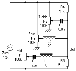
Source:
Duncan's Tone Stack Calculator
This tonestack differs considerably from the normal run by making use of inductors, L1 and L2.
To understand this circuit you only need to know that an inductor behaves in a conjugate or opposite sense to a capacitor, that is its reactance, XL, rises with frequency, according to;
XL = 2 π f L
This “similar but opposite” can be seen comparing the treble control R3C2 with the bass control R2L2.
In the treble control the capacitor blocks the lows, while in the bass control the inductor blocks the highs.
The mid network is a combination of both of the others, capacitor and inductor, but when we put these two opposites in the same circuit we get something we don't get with just resistance and capacitance, or resistance and inductance alone - resonance, in this case series resonance.
If we take the properties of capacitors and inductors given above, after a bit of algebra we get;
Fo = 1/(2 π SqRoot(L C))
In this case...
Fo = 1/(2 π SqRoot(6 22e-9)) = 438Hz
While Strauss used inductors in some of their tone controls they are generally unpopular and rare. The normal excuses are that they are prone to hum pickup, bulky, expensive, and more honestly, difficult to calculate.
To a large extent modern ferrite pot-cores have removed most of those objections, but they still tend to be ignored by home builders.
Anyone wanting to fiddle around with tonestacks, for real or just for fun, simply must download Duncan's Tone Stack Calculator.
This allows you to model Fender three-knob, Vox, Marshall, James, E-Series, Bench, and Big-Muff tonestack circuits. You can't change the circuit arrangements, but you can change any component value, source and load resistances, plot a nest of curves of the extreme settings, and compare plots.
It's a real tool aimed at those who are working out tonestacks for real, and Duncan's kindly provide it free. It runs well under W95 on old hardware.

