|
http://www.ozvalveamps.org/ava100/ava104redboard30.html | Created: 09/12/08 | Last update:
11:33 09/12/08
<<< OzValveAmps |
New: 9/12/08
The following is taken from an e-mail exchange between Ralph and Grant.
Ralph to Grant
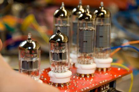
Here are some photos of my quad 6BQ5 amp build, based on our recent conversation.
I have dubbed it the “REDBOARD-30” - because it is constructed on red coloured Printed Circuit Board, of course!
I will write up some construction notes for the website. I have a very small number of these boards available should anyone else be interested in constructing. These first boards cost me nearly $50 each, but when you see the quality of them you will understand why - they are not the usual low-grade mass produced board. Like most things, ordering a larger quantity will bring the price down.
Although I have chosen to attach the valve sockets directly to the PCB there is no need to do so - short pigtails can be connected to regular sockets instead. I chose to solder the sockets directly, but using lead-free Tin/Silver/Copper (SAC) solder which has much improved resistance to fatigue from thermal cycles. What is important is that the board is designed to have the valves mounted on the rear side of the board.
Incidentally, my son (who is the guitarist in the family) absolutely loves the sound - it works a treat!
Grant to Ralph
Well done!! You have made a valuable contribution to the AVA100 project with your pcb design.
A few questions:
- 1. Are there any hum and stability issues with the amp?
- 2. What was the final HT voltage with your supply?
- 3. Have you measured power output?
Once again, well done, and for providing an opportunity to build this amp with the confidence of the pcb layout.
Will be very interested to read your construction notes. Also great to hear that your son votes the amp a success!
Ralph to Grant
There's a little hum, but not too objectionable. There is a tendency for the front end of the amp to self-oscillate at around 40KHz - I will need to resolve that issue, and I expect I can quieten it down by increasing the 100pF cap around the gain pot. [see below]
Frequency response of the overall amp is within 3dB from 60Hz to 60KHz, but peaks slightly at around 40KHz, hence the self-osc at this frequency.
HT voltage varies from 310V at no signal dropping only slightly down to 303V at full volume. Ripple is only about 3V.
I finished up using an LM1084-ADJ regulator for the DC supply - with a 910 and 100 resistors the supply provides EXACTLY 12.6v with unmeasurable ripple. The attached circuit explains.
At 1KHz there is 40.8V AC peak-to-peak measured on my scope, just at the onset of clipping, into a 10-ohm non inductive load. I am not sure how to convert this to RMS Watts. But the 10-ohm 15 watt resistor got incredibly hot after a short time.
Actually it is 43.2V - just measured it more accurately.
Grant to Ralph
For your reference, the power output is calculated by converting the 43.2Vp-p into RMS by firstly dividing it by 2 to reflect peak volts (21.6V peak) and then multiplying the peak figure by 0.707 to calculate RMS volts (15.27V RMS).
Power out then is Vrms squared (233.2) divided by the load impedance (10ohm) producing a power figure of 23.3 watts RMS - well done!
Would be interesting to parallel the 10 ohm load with a 39 ohm resistor to produce an 8 ohm load. This should produce even more power with an 8 ohm load. No wonder your load got pretty hot with this output power!
Note: this voltage is equal to 29 watts in an 8 ohm load.
Ralph to Grant
Thanks Grant for the help with the maths - that is how I'd thought it should be calculated, but I appreciate your confirmation. Interestingly, the current drawn (around 160mA or so) seems to confirm that this is about right for class AB1 at around 50% efficiency. This current is fairly constant, even under no signal conditions, and well within the capability of the power supply.
What do you think of the idea of increasing the 100pF cap to roll off the high frequency response, say to something like 15KHz? The high freq response it exhibits at the moment (>60KHz) is too high and leads to instability when the 'drive' pot is turned all the way up.

Also, enclosed is the PDF of the circuit - the components values are also marked on the PCB overlay.
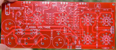
There is one errata - the PCB layout shows an 890R resistor on the silkscreen component overlay (part of the 12.6V regulator circuit) which should be a 910R (1% type). The schematic is correct.
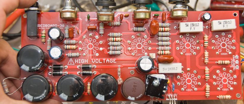
[photo of populated PCB, full size]
Roly to Ralph
Ralph: What do you think of the idea of increasing the 100pF cap to roll off the high frequency response, say to something like 15KHz? The high freq response it exhibits at the moment (>60KHz) is too high and leads to instability when the 'drive' pot is turned all the way up. [see below]
No. This will improve the high frequency response which is the last thing you want here.
In the first instance I'd try putting a small cap (say around 100pF [guess; more later]) across the anode load of the second 12AX7 section, your R6.
This will have the effect if reducing the anode load value seen by the section, thus reducing the gain, at higher frequencies. For best results this cap may also require a resistor in series with it so it doesn't start to roll the response off too low, but for a guitar amp a 15kHz knee should be fine given that typical guitar speakers roll off a lot lower than that.
Very well done - big hat tip and thank you.
I have had several e-mails from builders-in-progress who said they found the AVA100 idea “inspiring”. Well, it's hard to imagine what else could be more inspiring than having a PCB available. It won't make you rich, but I'm sure that if you make a board available you will get at least a few takers for what what could be considered as a Vox AC-30 clone.
|
|