http://www.ozvalveamps.org/ampstages.html | Created: 28/08/06 | Last update:
15:04 5/01/11
<<< OzValveAmps
|
Amplifier Stages
Australian valve guitar amplifier practice of the 1970's, taken stage by stage from the input sockets to the speaker socket.
A guide for repair and design.
Contains:
|
Inputs, Channels, Input stage, Tone and EQ, Effects, Tremolo/Vibrato, Oscillator, Reverberation, Line in/out, Channel mixing, Voltage Amp Stage, Phase Inverters, Drivers, Output stage, Transformer basics, Output transformer, Power supplies
|
Inputs
The XLR or Cannon-type connector is clearly a better audio connector than a 6.5mm jack plug and socket, but tradition makes the 6.5mm socket mandatory despite its serious connection problems.
Inputs range from a single socket connected directly to the grid of the first stage, no resistors or blocking cap (Marshall PA); and up to six (Vox AC-30 II), all different.
|
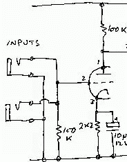
This example has a fairly low input resistance of 100k but is otherwise direct-connected to the input.
This low input resistance would be most unsatisfactory for an acoustic guitar with a direct piezo pickup and would sound very thin.
This circuit provides no protection against radio frequency (RF) breakthrough.
Any leakage from an active guitar or effects pedal will upset the self-bias on the first stage.
|
|
If more than one input socket is provided it is normal that they will have different characteristics.
|
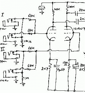
This Strauss, for example has four, two high and two low level, and as two full bandwidth, and two for “lead” bandwidth.
When the input is plugged into the upper socket the input has 1M to ground and two 68k in parallel, 34k, in series. In the lower input the input resistance is two 68k in series, 136k, and divides the input in half (-6dB).
The first would suit a guitar magnetic pickup direct, and the second is effectively a line level and impedance input, so it would suit a stomp box output.
The cathode bypass capacitor on the lead channel is much lower value, 0.67uF, causing more AC negative feedback across the 2k7 at lower frequencies, so producing a 'toppy' channel. The outputs are mixed downstream.
Note: the 180 ohm cathode resistor is more likely a 1k8.
|
|
Another arrangement is three inputs, one flat for keyboards, one bass cut for lead guitar, and one treble cut for bass (Playmaster).
Switch contacts on input sockets are used in many different, cunning and obscure ways to alter input impedance as well as sensitivity (Trent, Strauss).
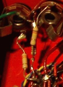
Ideally the common of the socket should be isolated from the chassis to prevent earth loops. Commonly available isolated sockets are not nearly robust enough for guitar input service. XLR's are tougher, but they don't come with switch contacts.
A discussion of how to get around this grounding problem.
Channels
Simple amps have only one amplifier channel even when they have a lot of input sockets. Different signals are mixed early in the chain and amplified together.

Normally guitar amps are used by only one instrument at a time and multiple input situations are 'emergencies', so this is not important.
More complex amplifiers provide two or more channels. Normally they were an un-effected channel with its own tone and volume controls; and an effected channel with its own controls including reverb and tremolo/vibrato. These were then mixed into the main power amplifier.
A more modern idea is to have channel switching in the amp that allows selection of two (or more) groups of front panel settings.
There is no reason why channel switching cannot be applied to a valve amp if desired, but it is important to have an 'at-a-glance' indicator to show you which channel is selected.
Input stage
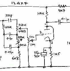
The first amplifying stage in guitar amps are pretty much the same, half a 12AX7 in an almost standard stage.
|
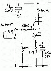
A single shorting jack socket to minimise noise with no input.
The 1Meg input resistor provides a light loading for the instrument, and while it's still a bit low for accoustic piezo pickups it is adequate.
The 68k resistor is an RF 'stopper' to prevent radio signals being detected in the first stage.
The anode and cathode resistors are typically 100k and 1k5 as shown, or 220k and 2k2, always with a 25uF/25V bypass. This was not a great choice since they only have around 2 volts on them in operation. Failures may be rare but they may not be bypassing audio to their best either.
There may be some benefit from using a voltage rating closer to the actual operating voltage. As a rule of thumb electros should operate at more than half their rated voltage so they 'form up' correctly. The value tolerance on typical electros of the era, for example Elna, was -50%/+100%.
|
|
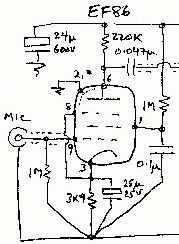
Another input stage was the low-noise pentode, popular in microphone amp use in PA's and the like.
|
The EF86 shown here was a specific low-noise front-end amp, but other pentodes such as the 6AU6 have been used. A pentode provides considerably more voltage gain than a single triode stage e.g. x200 against x50.
The single-point earth was literal with these stages, all earth returns brought back to a single common point near the valve base, sometimes a metal cylinder in the middle of the valve base. Octal sockets sometimes had four inviting grounding lugs formed into the base mounting ring with the same general idea, but generally not as effective (particuarly at RF).
The HT supply should mirror the grounding and should also be single-point, the two ends of the 24uF bypass cap being the two common points, hopefully shorted together to AC by the cap.
The gizmo in the top/left of the valve is an internal electrostatic screen which is connected to the common ground point.
In PA mic preamp service these were sometimes mounted on a sub-chassis, in cages and sometimes boxes, floating and insulated with rubber grommet shock mounts to prevent microphony.
|
|
Valve Screening
Preamp valves are prone to microphonics, Radio Frequency rectification, capacitive pickup, and magnetic pickup, so are normally fitted with some form of shielding can.
This ranges from a simple curl of aluminium with a wire clip retainer, to lock-down blackened steel with internal seating spring and copper heat transfer fingers.
The two most common forms are i) a twist-lock like an inside-out lightglobe bayonet connector, and ii) a snap-on form with a constriction around the bottom that snaps over a matching rib in the skirt around the base. Snap-on are far superior to the flimsy twist-lock.
The object of these cans is to prevent direct capacitive pickup by the internal elements of the valve. Steel cans also provide some magnetic screening.
The strong local magnetic hum field that leaks from the power transformer will modulate the electron beams in any nearby valves, with unpredictable effects. Ideally all valves, including power valves, should be clear of any nearby transformers, including output transformers.
Microphonics are caused by the wires of the control grid vibrating sympathetically to outside vibrations, and causing variations in valve current as a result. These short wires vibrating un-damped in a vacuume may even produce high-pitched feedback.
All valves are microphonic to some degree, and can be swapped to less critical stages such as the phase inverter, but in serious cases replacement is the only answer.
RF-rectification, that is AM broadcast or CB'er break-through, is caused by detection in the first stage. Generally an RF stopper resistor right on the grid pin will suffice.
In more serious cases ferrite beads can be put on the input lead, and a shunt RF by-pass of 47pF to 100pF between grid and cathode will generally shut it up. In extreme cases speaker and power lines may also need treatment. Consult the A.R.R.L. or R.S.G.B. Handbooks.
Tarnished or slack valve socket connectors are a major cause of crackles, frying noises, and loud blurts if the valve is moved or the case thumped. Careful cleaning and contact re-tensioning will generally fix this.
CRO tube shields are a special case. If you are working on your Oscilloscope or any other gear that has a CRT in a metal shielding tube, treat the shield itself as glass. It's made out of 'mu-metal', an alloy that is highly magnetically conductive. Do not knock, hammer, drill grind or stick a magnet to it or you will destroy its magnetic shielding properties.
Tone, EQ
All guitar amps have some form of tone controls, these days called “tonestacks”, or EQ - equalisation of response.
Prejudice 1. - (also held by Carvin*) an amp should give reasonable results with all the controls set for mid-point, 5 (or 6 for Marshalls ;)
Prejudice 2. - if you normally have to crank in a lot of EQ, something else is wrong. Fix that first; no amount of EQ can put back what isn't there, pickup response, cable loss, speaker response, etc. (see Cube-40)
Tonestacks are where the greatest opportunity for creativity in design exists and therefore variability will be found, where the designer has tried to make their mark.
Tone control requirements for a guitar amp are quite different from home Hi-Fi, PA, or keyboard amp where the aim is reasonably flat response.
In guitar amps tonestack networks do anything BUT equalise frequency response. In fact it seems that the characteristic favoured by most guitarists has a default mid-band scoop, or cut.
|
The frequently copied Fender-type tonestack shown here is pretty well impossible to set to a flat response. The controls tend to act a raw volume controls in their respective bands. With them all down you get next to nothing which can be a trap when testing.
Like most popular guitar tonestacks these have a significant mid-band dip. To set a Fender-style three-way reasonably flat set treble to 2, mid to 10, bass to 2.
In this direct-coupled arrangement a few microamps of grid current will flow in all the control wipers. This can sometimes lead to 'wiper noise' when the pot is moved. It is therefore generally good policy to keep DC off pots carrying signals.
|
|
The general order of popularity of topologies to copy or derive from is:
Some, like Strauss, seemed to have their own ideas and others, particularly homebuilds, were creative, imaginative, ignorant, crazy, som'thin else. This can give rise to considerable confusion (“...huh???”) if you are dealing with a design that didn't work from the start. People do build and even sell amps like that. (see Savage, Lenard)
Baxandall-type feedback controls are rare on guitar amps being both fairly new and their contour action is not really suited to guitar.
The general action of a passive control is to hinge the response around a hinge frequency, typically 1kHz in Hi-Fi, but often lower around 440Hz (the “A” above Middle-C) in guitar amps. Boost or cut is applied progressively from this frequency. Naturally three-knob stacks have two hinge frequencies, low-mid and mid-high.
The main advantage of the Baxandall arrangement is that it reduces the control interaction found in many passive tonestacks.
The active Baxandall (not shown here) applies NFB to the end of the network that is normally grounded in the passive version. This changes its operation considerably and it no longer hinges, but introduces a fairly steep degree of cut or boost, initially only at the extremes of frequency, but with more EQ the cut or boost moves closer to the hinge. In doing so it applies huge degrees of cut or boost to the frequency extremes.
This works well for home stereos but is a bit of a disaster in music instrument amps. In some ways the Baxandall represents the opposite pole to Parametric EQ (below).
Where a “presence” control is fitted (Strauss, Moody) it may be clustered with the tone controls but this generally acts on the main negative feedback loop around the output stage. It's actually in quite a different part of the signal path.
Graphic EQ
So-called graphic EQ's are common on modern amps but were generally a bit difficult with valves to appear in anything more than the most basic form, Strauss again (below).
A couple of general points about graphics.
What you see is not what you get. For gentle contours the graphic representation of the sliders is a pretty reasonable approximation of the actual passband. But who uses them like that?
I saw one DJ operating with all his even sliders full down and odd sliders full up. Okay, this is extreme and stupid, but it serves to illustrate the fact that each channel has an adjacent-channel skirt response in the channels above and below, and in the vast majority of units this is far from inconsiderable.
In this case the resulting overall response would actually be fairly close to flat, albeit with some serious ripple, but nothing remotely like the graphic display. The ability of most units to notch out or brick-wall is more limited than the display would lead you to think.
What you get is not what you see. Even set dead flat for amplitude response the phase response still goes though a full rotation for every channel. If you care about time alignment you may care to think about that.
In my view the role of a graphic EQ is in the foldback channel where even a limited ability to dip a peaky microphone can be very useful, just don't assume that you are really getting the bandpass you see.
Parametric EQ
Parametrics were unknown in the valve era. They take a little learning to drive but are capable of rather magical results, particularly with recording mixdowns.
A parametric band control can be recognised by the extra controls its has apart from just the cut and boost control. It will have a frequency control that allows the center point of the control to be tuned up and down, and may also have a “Q” control that alters the sharpness of its response from wide to narrow.
Typical Parametric control setups range from:
- a single channel tunable over most of the audio range,
- parametric mid-band control combined with conventional shelving bass and treble controls,
- dual parametrics with overlapping tuning in the mid-band and shelving highs and lows,
- or three parametrics with overlapping ranges spread from high to low.
While parametric type controls are capable of creating very sharp peaks and notches in reponse it is their ability to fairly specifically but gently encourage or discourage a specific band of frequencies that makes them special for the sound engineer.
While new forms of EQ have emerged based around the simplicity of silicon op-amps, there is no conceptual reason why such circuits could not be built using valve op-amps, parametrics in particular.
Tonestacks like to be fed from a low impedance and work into a light high impedance load.
|
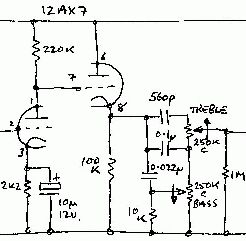
In this arrangement the second half of a 12AX7 is used as a unity-gain cathode-follower to drive the tone network from a low (Z~1k) impedance, but ~50k from the anode of a gain stage is more common.
(note there is a missing 100k in this tonestack between the 560pF and the 0.1uF)
|
|
Tonestacks are frequency-selective because of the ratios of the components. This means they are scalable to different values as long as the correct ratios are maintained.
In practical terms the designer must find a balance between the source and load impedances for satisfactory tonestack operation. The stack needs be higher impedance than the source, but less than the load.
Failure to observe these constraints will result in a tonestack that does not work as designed.
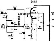
This circuit shows a passive Baxandall tone arrangement followed by a pentode as the Voltage Amplifer Stage (VAS), and Negative Feedback (NFB) summing amplifier, as used in the Playmaster 116/7 guitar amps.
|
In this case the loading due to the valve grid is very low indeed, being virtually open circuit.
The Baxandall is sometimes simplified with a single cap across the bass control rather than the two to the wiper.
NFB comes from the speaker winding of the output transformer and is applied to the cathode circuit across the 220 ohm resistor.
This causes the stage to sum the input and NFB voltages as its grid-to-cathode voltage.
Typical feedback levels in a valve guitar amp are 12 to 15dB, but may be quite a bit lower, say 6dB, or even none at all.
|
|
Resonant
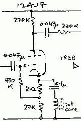
This is one of the more unusual tone circuits, consisting of two identical stages with a series-resonant circuit as the cathode bypass.
|
One of two identical stages from a Strauss PA with level controls marked 'treble' and 'bass'.
The key is the series-LC circuit in the cathode.
Around its resonant frequency its impedance falls to a minimum. This causes the stage gain to rise to a maximum, thus providing a fixed 'hump' response that could be turned up or down.
It's a bit like a parametric EQ with fixed centre frequency and low 'Q' and variable output. In this case the centre frequency could be set using an adjustor in the ferrite potcore inductor.
|
|
Effects
Audio effects on valve guitar amps were limited to tremolo/“vibrato”, and reverberation.
“Vibrato”/Tremolo
Somewhere in the surf-music era these old musical terms got mixed up, so we have amplifiers with a “vibrato” control and guitars with “tremolo” arms (now more often called whang- or whammy-bars).
Tremolo, or on old pedal organs tremulant, actually means a gentle regular modulation of signal amplitude or loudness.
This is what you get if you rapidly rock your guitar volume control up and down.
Vibrato actually means a gentle regular modulation of signal frequency or pitch.
This is what you get with the whang-bar, bending a string, or pulling back on the neck of the guitar.
How these came to be reversed can only be guessed. In the individual amplifer descriptions here the names used follow what the manufacturer used, but on this page the conventional musical definitions, above, will be followed.
As far as I know, none of the classic Australian valve amps used vibrato or pitch shifting. Whatever they called it, all used tremolo or amplitude modulation. If you know of an exception, even home-brew, I'd like to hear of it for inclusion here.
It should be noted that a change in loudness produces a subjective change in pitch, which is quite significant. A rapid drop in level produces an apparent raising of pitch. The reverse is real, but not as obvious because of the automatic gain control function of human hearing.
You can easily demonstrate this by listening to some music on headphones (only) at a fairly high level for long enough for your ears to adjust, then rapidly removing the headphones or quickly turning down the volume.
See also Modulation.
Oscillator
Beit vibrato or tremolo, a low frequency oscillator or LFO is required which generally produces a sinewave adjustable from roughly 1 to 10 Hz, however this modulating signal may be quite distorted and may even come from a squarewave oscillator.
The most common form of oscillator used is the phase shift oscillator.
|
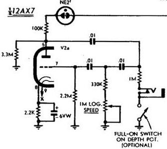
The circuit oscillates due to the three-stage RC feedback network which shifts the phase of the signal from the anode by 180 degrees at the frequency of oscillation, and applies it to the grid.
The valve inverts the signal another 180 degrees so the total shift around the loop is 360 degrees and the feedback therefore positive. It also provides gain to overcome the considerable losses around the loop.
Each RC element produces a 60 degree phase shift, and by making one of the elements variable the frequency can be tuned. It is possible for the network to have more then three RC elements but it is rare.
This network also attenuates the signal by about 1/3 in each leg, so the overall loss is about 1/27 meaning the amplifier must have a voltage gain of at least 27 for the circuit to oscillate.
|
Playmaster 116/7 Errata: Ck = 25uF
Signal output is via the NE-2 neon in series with the oscillator supply. The 3M3 prevents the neon extinguishing and producing thumps. A footswitch plugs into the jack socket for remote control.
|
In all oscillators the level of oscillation rises until something limits it.
In this case the limiting factor is amplifier clipping causing the stage gain to fall off. This means that the waveform produced is not a very pure sinewave, and may in fact have considerable distortion and flattening on one peak.
Symptoms of insufficient stage gain include:
- not starting
- sluggish starting
- dropping out at some frequencies (however this may also be caused by a noisy “speed” pot)
Excessive gain can cause:
- choppy effect
- clicking or popping at effect speed
If required the gain can be trimmed down by inserting a small resistor in series with the cathode bypass capacitor, but you need to check that the oscillator will still start reliably under all settings and conditions.
For some example circuits see:
Playmaster 116,
LDR Amplitude Modulation 12AX7, 6X4.
Solid state:
LDR Amplitude Modulation,
3 x LDR PM phase vibrato. This latter is of particular interest because it is one of very few examples of an actual pitch-shifting vibrato circuit. A developed and current design using FET's can be found on Rod Elliot's ESP site.
For more on oscillation see Stability.
Reverberation
In the valve era there were two delay effects, reverberation, a short delay supplied by a spring-line reverb 'tank' generally mounted in the floor of the combo cabinet in some form of soundproofing; and echo, supplied by a tape loop and multi-head replay.
The reverb line or 'tank' consists of a spring suspended between a magnetic driver and a magnetic pickup.
The driver acts as a small loudspeaker and the sound is launched along the spring where it takes some milliseconds to get to the pickup.
This is the basic delay. By itself it would be a bit boring, so all sorts of tricks are used to make it more sonically interesting like a real environment.
Most units consist of four springs with slightly different pitch, tension, diameter, material, whatever. The sound travels at different speeds in each case and also reflects off the spring joins as well as the ends.
These are normally strung as a pair of springlines, each with two different springs end-to-end, held by a taught-wire suspension with bonded-on cylindrical magnets, magnetised crossways, not end-to-end like a bar magnet.
The waves launched by the sender also reflect off the receiver and the joins in the middle, so a very complex set of decaying waves bounce back and forth along the lines.
While a simple push-pull along the line of the spring works, launching along the wire is better, so the spring is driven with a rotary motion, endways to the wire.
Both the driver and pickup are very elementary magnetic circuits. The main difference is the impedance of the coils, so lines have a definite input and output. The plugs to reverb lines are normally RCA's and can be, and sometimes are, reversed by somebody cleaning inside, fiddling, etc., something to check if the complaint is weak reverb.
Another point to watch is tank grounding. To avoid creating an earth loop between the reverb driver and the recovery amp generally only one signal screen is connected to the tank frame. And this often with a rivet by compression. These can work loose and produce severe intermittant microphonics.
A more common problem are the fine wires used to carry the signals between the sockets on the tank case and the coils on the internal shock frame. These can break but not look broken, and need to be tested with a light tug.
Spring reverb tanks are actually quite fragile and don't like road work. If you open a line and find the spring(s) sloshing loose, look carefully around the inside for one or more of the drive magnets stuck to the case. It will look like a little brown mouse turd with a silver hook through the middle. The suspension wire normally breaks just behind the magnet and I've yet to repair one, but if by chance it still has a tail to use you might get lucky.
Addendum 5/1/11:
How to repair a broken springline.
Some tanks have an arrest or transportation lever on the side that clamps all the floating parts with padding. These are a great idea if you can retro-fit, but you must remember to use it, and never release the line with the amp 'live' unless you want to deafen yourself.
|
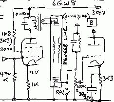
The reverb drive stage is normally a single-ended, class-A, transformer-coupled power stage. This may be a small power 7-pin pentode, pentode-triode (6GW8), or paralleled twin-triode (12A?7).
A recovery voltage amp is required for the pickup and is often surrounded by frequency compensation networks (0.0047u, 22k, f0 = 1/2 Pi RC, = 1540Hz), and reverb effect switching.
The 0.001uF cap across the drive transformer primary is prone to short-circuit failure and is often a 600 volt DC working, or higher, component.
|
|
Detail on the operation of springline reverberation tanks.
Reverb circuits and applications.
In Silicon Chip Jan 2000 John Clarke covered reverb lines in depth including the use of current drive for 'better' operation. See also 'Spring Reverb Unit For Guitar' at ESP.
Detail on tape loop echo machines.
Line in/out
Few amps of this vintage had line-in/-out or Fx loop facilities. One notable exception is the Maton Studio.
Common retrofit 1:
Take the top end of the volume control via screened cable to a socket on the back. now you have both Line-In and Out!
Variation: tap a cap off the anode.
Common retrofit 2:
Resistor divider across the speaker winding, to a socket.
Problem 1: this can make solid-state unhappy by i) high voltage charging surges at connection or switch-on; and ii) potentially very high signal levels, 100V+ peak.
Problem 2: works, but speakers also act as mikes, impressing environment noise on the signal.
Channel mixing
When the amplifier has two input channels the outputs of those channels have to be mixed to be fed into the main power amp.

In this example the Lead channel comes in from above while the Normal channel comes in from below. The caps and resistors are chosen to give top-lift and extra gain to the lead channel. Note that in normal use signals will only be coming from one channel at a time.
Voltage Amplification Stage
There is sometimes a Voltage Amplification Stage (VAS) following the channel mixer and before the phase inverter, and if fitted this is normally where the output stage Negative Feedback (NFB) is summed.
Feedback
This NFB comes from the output transformer secondary via a dropping resistor that sets the overall NFB level.
Strictly this is voltage feedback because it is taken from across the load.
Another form of feedback is current feedback which is derived from across a resistor in series with the load, so the current feedback signal is a voltage that is proportional to the current in the load. This reduces damping of the loudspeaker or allows it to be varied.
This was rarely used even in Hi-Fi amps and I know of only one valve guitar amp that used variable damping, a KT88 bass amp I built in the 70's.
There is renewed interest in amps using a combination of voltage and current feedback in roughly 90/10% proportions because this can make solid-state amplifiers sound much more valve-like. Rod Elliot's ESP site has such a design.
Phase splitters or Inverters - PI
A push-pull output stage requires two identical, but opposite, drive signals.
Strictly speaking 'phase' means time delay, and there is none here. What we actually have is the signal and the voltage-inversion of the signal, but I'll stick with the “PI” shorthand convention.
Split-Load
|
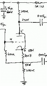
The 'split-load' phase inverter, so-called because the valve load is split equally between its anode and cathode circuits.
The signals at these points are complimentary, equal but opposite in voltage.
The load resistors are often a lot lower than the 100k shown so this stage tends to get worked hardest of the preamp stages.
While this a nice simple solution it can lack sufficient voltage swing for lower gain output valves and higher bias voltages.
|
|
Cathode-coupled
|
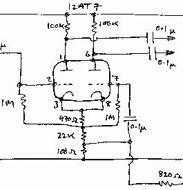
A cathode-coupled phase inverter, or differential amp as it is called when used in transistor power amps. Also known as a Long-Tailed Pair or LTP.
The second stage acts to keep the current in the cathode resistors constant.
It mirrors the current in the first stage and its anode voltage is an inversion of the first stage anode voltage.
NFB is summed into the stage across the 100 ohm cathode resistor.
|
|
Unity-gain Inverter
|
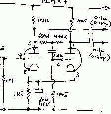
While both stages share a cathode resistor, it is bypassed by the 10u/12V electro, so this in not to be confused with the cathode-coupled, above.
The first stage is a conventional gain stage. The second stage is a unity-gain inverting stage.
Forward signal via the 680k resistor is balanced by feedback via the 470k resistor, ideally resulting in zero grid signal at pin 2.
In reality these resistor values have to be slightly unequal to get equal signal levels out. In some cases these resistors are equal but the anode loads aren't, to the same effect.
|
|
Leaky grid
|
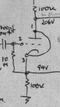
This variant of the split load phase inverter uses contact bias rather than the more common cathode bias.
In this case negative bias accumulaates on the grid because it can only leak away through a very high value resistor, here 10M.
Because of this very high input resistance the stage is prone to bias upset from leakage through the input capacitor, and to aging effects in both the valve and grid resistor.
|
|
Drivers
In higher power amplifiers the output valve grids require a larger voltage swing, or in the case of classes AB2 and B2 a small amount of grid current.
|
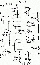
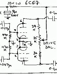
This is a very straightforward amplifier stage for each of the drive signals.
The drive is balanced by the control between the driver grids.
A small amount of local NFB is applied due to the 150 ohm cathode resistor.
The 6CG7 is a medium power twin triode common in this service, though 12AT7's have been used.
If the pot wiper should fail open the stage will only be a bit unbalanced.
|
|
|
In this driver the output is balanced by an adjustable anode load. While this works, it dissipates power in the pot, heating it up.
If the pot wiper should fail open the stage will stop working.
|
|
Output Stages
Class-A, Single ended
Valve current flows for the full input cycle.
All preamp stages operate in Class-A.
The single-ended output stage is used in very small amps of the 'practice' type and has a very low power output.
Please note carefully that Class-A does not mean cathode bias, nor does cathode bias mean Class-A operation. The output stage of the Vox AC-30 uses cathode bias and many people refer to it as Class-A, but it isn't, it's under-biassed Class-AB1 (see below).
One of the advantages of a Class-A output stage is that it has no crossover distortion, although it is likely to be significantly non-linear in other ways.
|
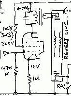
The driver for a springline reverb is a single-ended Class-A power amp, in this case the pentode section of a 6GW8.
Local NFB is applied to the stage by not by-passing the 1k cathode resistor.
|
|
Push-pull, Class AB1
Valve current flows for more than half the input cycle, but less than a full cycle. The valves idle at maximum power dissipation. No grid current.
Cathode Bias
|
This example happens to be cathode-biassed using a resistor in the cathodes to develop bias, its value setting the stage operating point.
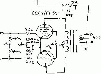
This arrangement was popular in 40 watt amps.
Note the 100pF stability cap across the 15k NFB resistor. This cap can be chosen by driving the stage with a low level squarewave and tweeking the value for squarest output.
Failure of the cathode bypass electro short circuit will take both output valves with it. Replacement should be with a new unit with sufficient ripple current rating.
|
|
Fixed Bias
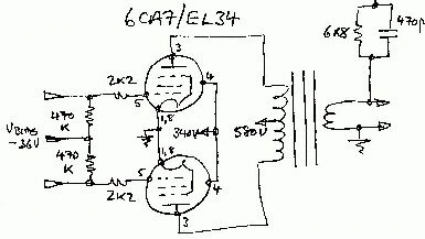
This was a common 60 watt arrangement.
|
Much the same as above except this stage uses fixed bias from an external negative bias supply. 'Negative' simply means its positive side is grounded, and the normally grounded negative is taken as the supply. Watch for diode and electro polarity when testing or replacing.
The health of the bias supply is critical to avoid melting the power valves and should always be checked as part of servicing.
|
|
The 2k2 resistors in the control grids (more often 1k5's) are RF stoppers to prevent radio frequency oscillations from breaking out locally around each valve. These should be fitted hard on the valve socket grid-1 connection.
Low value resistors or even chokes fitted right at the anode connections (807's) have the same function, and stop the stage bursting into RF oscillation at some point of the half-cycle.
|
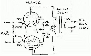
Again similar to the above, this 6L6 stage has individual resistors feeding each screen grid, which is getting closer to the textbook.
Note the screen supplies are often half the anode supply voltage, but you also see amps where the screens are dropped via resistors directly from the main supply if its below about 400 volts.
Errata: naturally the cathodes are grounded.
|
|
Push-pull, Class AB2
Valve current flows for more than half the input cycle, but less than a full cycle. The valves idle at maximum power dissipation. Grid current flows on peaks meaning power drive is required. These are often transformer-driven.
Push-pull, Class B1
Class-B operation can produce more output power than the sum of the anode ratings implies, however this is at the expense of considerable crossover distortion.
While this is acceptable in a factory PA or Ham radio modulator it is generally unacceptable for stage use.
Valve current flows for slightly less than half, but most of, the input half-cycle. The valves idle cut-off. No grid current flows.
Push-pull, Class B2
Valve current flows for slightly less than half, but most of, the input half-cycle. The valves idle cut-off. Considerable grid current flows on peaks requiring power drive (see AB2 above).
Higher Classes exist but are not used in audio work. These is Class-C where conduction occurs only over a very small portion of the cycle and depends on a resonant load to restore the waveshape. This mode is generally only used in transmitter output stages.
Class-D is pure squarewave switching mode with a low duty cycle or on-to-off ratio, with similar considerations to Class-C.
Other Classes are generally marketing inventions like PMPO.
Multiple pairs
A number of amps have been built using multiple pairs of output valves to get higher power. This is called 'parallel push-pull' and commercial amps were built with three and four pairs of output valves.
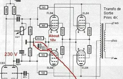
Vox AC30
In this arrangement the plate-to-plate impedance is half the value for a single pair, and the supply current is doubled. For Class-AB1 the same bias supply and driver are normally sufficient because the stage is purely voltage-driven and no grid current, and therefore power, is required.
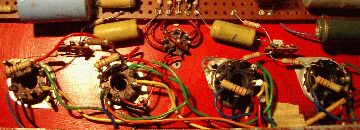
Click for full size 340kb jpg
A Trent output stage. Strauss also liked push-pull parallel.
The twin-triode phase-inverter/driver is top centre with its output coupling caps either side, and grid resistors alongside. Two grid stoppers each side then carry the bias and signal to the actual power amp grids.
The 1W resistors mounted on the bases are the screen feed resistors, typically using a spare valve pin as a tie point.
Take care using valve pins as tie points; on valve base diagrammes “I.C.” means Internal Connection and must not be used, while “N.C.” means No Connection and may possibly be used.
There are a couple of traps with doing this. For example, you would not use a pin as a tie in the grid circuit if the next pin was the anode carrying hundreds of volts of signal. Best to treat anode circuits as extra high voltage and give them twice the normal spacing.
People sometimes try to substitute different output valves. Even where this is done with some care such as looking up the valve base connections, it is easy to miss that an unused pin has been used as a tie point in a particular amplifier. See Strauss - unhappy Lancer 6CA7 to 7027A mod.
Transformer basics
You will find transformer theory elsewhere, but the basic point to keep in mind is that a transformer transforms the load it sees on one side, to the driving side.
Power is conserved; you can't get more out than you put in, so the product of voltage and current, E x I, on both sides will be the same (less losses).
A vital parameter is the VA-rating of the core or lamination stack. This defines the upper limit of power that the transformer can carry without overheating.
It acts very like a gearbox in that it transforms high speed and low torque to low speed and high torque. Like a gearbox, at least in theory, transformers are bi-lateral, that is they work both ways, and which side is input/primary and output/secondary is arbitary to the application.
Note that practical power transformers, small ones in particular, tend to be optimised for operation in one direction (the intended primary is wound on first) and may prove lossy if run 'in reverse'.
The transformer reflects the load conditions it 'sees' on one winding (secondary, speaker side), as a load on the other winding (primary, valve side). When we say an output transformer has an impedance of 3.2k plate-to-plate what we mean is that the load (speaker) impedance is reflected through the transformer to the valves as an effective impedance of 3.2k p-p.
Transformers have high to very high coupling and therefore efficiency (85-95 percent, better as they get bigger). But they aren't perfect and some magnetising current flows in the primary due mainly to eddy-current losses in the core lamination material even when the secondary is unloaded.
These are called iron losses. Losses under load come from I2R losses in the winding resistances and are called copper losses. Iron losses are constant for a given tranny while copper losses depend on the loading.
The voltage 'gear ratio' between windings is simply the turns ratio of the windings.
Since power is constant the current also is the turns-ratio, but inverse - lower voltage means higher current.
Output Transformers
The output transformer is a key component in a valve amplifier. A good output tranny is vastly different to a power transformer.
Never operate a valve amplifer without a suitable load securely connected.
Never probe the anode circuit under drive.
A major cause of output transformer failure is driving the amplifier without a load connected. Very high voltages can be induced, causing flashover internally and ruining the transformer.
These days replacement transformers can be hard to find, are always difficult to physically replace, which makes repair expensive. For many classic valve amps this has been the end of the road, and most of the dead chassis I see are missing the output transformer and showing evidence of a cook-up where it had been. Very sad, but once again worth attention by a restorer.
|
In this Goldentone chassis the original 6DQ6's have been replaced by 6CA7/EL34's.
The 6DQ6 has its anode on a top cap, hence the neat flying anode wiring from the top of the tranny to underchassis where the 6CA7 anode pins are located.
|
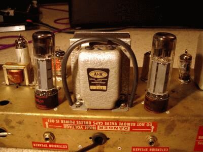
Source: Shaun Helps
|
An output transformers steel laminations are generally thinner than a mains tranny to reduce eddy-current losses at high frequencies, and which are stamped grain-oriented from the original strip, following the line of least magnetic resistance through the steel.
Most transformers are made with “waste-less” stampings where two I's are the gaps in two E's that face each other. This gives rise to the stack ratios in common use. Variant cores include “ballast” type (long), C-core (one-sided), and torroidal (inside) types.
Input Tappings
A conventional push-pull output transformer has three connections to the primary (valve side), two ends with a centre-tap.
The main HT is applied at the centre tap and the anodes connected to the winding ends.
Primary impedances are quoted in ohms plate-to-plate, that is end-to-end across the whole primary winding.
Some transformers have two more tappings near the mid-point of each side of the winding. These are to provide screen voltage in ultra-linear connection, a mode of operation somewhere between pentode and triode.
While this is rare in commercial guitar amps it is not unknown in some homebrew rigs. Ultra-linear connection generally produces somewhat less (20-30%) output power than normal pentode connection. The most common tapping is around 46% which suits 6CA7/EL34's, but the optimum tap position depends on the valve type, KT88's requiring around 20%.
Some manufacturers also made combined or general purpose transformers that also had taps on the primary, but these were generally only a small percentage (~10%) in from each end. These were something like 10k/8k p-p or 8k/6k p-p to suit a range of output valves.
Output tappings
Most commercial guitar amps provided only one output impedance - typically 8 ohms, although 4 and 15 were also used.
A&R-Sonar used the following colour codes for multiple secondary tappings:
| Black | Common |
| Brown | 4 ohms |
| Yellow | 8 ohms |
| White | 16 ohms |
Connectors
These output impedances are nominal and you may see 16, 8, 4 given as 15, 7.5 and 3.75 ohms. These series are effectively equal.
At these power levels and load impedances the currents grow to be several amps. Most of the amplifiers of the period used 1/4-inch or 6.5mm jack plugs and sockets as output connectors. These are a rather poor choice for this sort of duty and frequently make bad connection, leading to loud crackles. Worse, they can lead to a blown output transformer.
XLR's may not be true to the period ('tho found on some amps like Strauss) but they are a far better proposition.
Feedback connection
This is normally taken from across the secondary winding, but may come from a specific tertiary winding in PA applications such as 100 volt line.
Power Supplies
The Power Supply Unit (PSU) has to provide several voltages at considerable power levels to a valve amplifier.
Supplies such as these may give a deadly electric shock hours after disconnection from the mains. ALWAYS discharge PSU caps with a lamp load before commencing work.
Mains wiring in these amps was normally exposed. Identify, check, and repair before plugging in.
Bi-Phase
This is a bi-phase full wave rectifier. It may use silicon diodes, as here, or a double-diode valve.

Note the power resistor which limits the switch-on surge current while the caps charge, and provides a little “sag” under drive. Typical of Moody.
Smaller amps generally used indirectly heated rectifiers like 6V4 and 6X5, and larger amps generally used the directly heated type. An early very common type was the 80, superceeded by the trimmed-down octal 5Y3 in a 6V6-size envelope. In indirect heating the heater is (somewhat) isolated from the cathode; but in the latter the heater is also the cathode.
Expect all valve rectifiers heaters to be at full supply voltage.
Voltage doubler
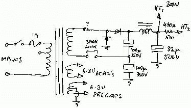
This is a voltage doubler. This arrangement became more popular towards the end of the classic valve era as transformer choices narrowed but capacitor choices widened.
|
Note: that the body of the upper cap must be well insulated from the chassis or accidental contact!
The centre tap on the heater winding is to balance it to chassis to reduce hum from the heater wiring.
The choke filter has good rejection of hum and higher-order products produced by rectification, together with a low DC resistance. Chokes have their rated inductance at a given DC current.
|
|
Complex bridge
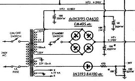
This common arrangement can be confusing in operation.
|
The main HT is a bridge rectifier using the whole winding.
At the centre-tap it looks like a normal bi-phase rectifier, except that the diodes are reversed in the grounded leg. The output is half the main HT voltage and is used for the screen and preamp supply.
Note the tertiary winding for the bias supply, doing away with the need for a small separate bias transformer so often used.
Bias supplies are almost always half-wave due to the very low current drain.
|
From: Playmaster 116/7
|
For more on power supplies see voltage regulator tubes.
How to bring the power mains safely into your amp.
* The Carvin catalogue impressed me because they give their speaker cab response curves (10 points) in a form you can actually read (10 points) and unlike some manufacturers of sound gear (B...........) they look totally realistic (50 points).
 <<<OzValveAmps
http://www.ozvalveamps.org/ampstages.html | Last update:
03:02 28/08/06
|


