|
http://www.ozvalveamps.org/moody.html | Last update:
2017/08/04
<<<OzValveAmps |
R.Moody and Co. Pty. Ltd., Sydney
Contains:| Echomaster, 60W (GA60?), GA40 & cabinet, Ultratone Custom 40, BA40, GA-35, BA-17, GA12 Vibralux 10/12, 496, Mystery. |
New: 7/7/11
Source: “thewaxpig” - AGGH
New: 30/9/08
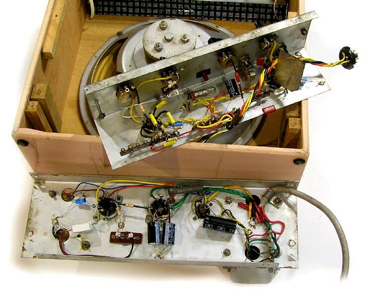
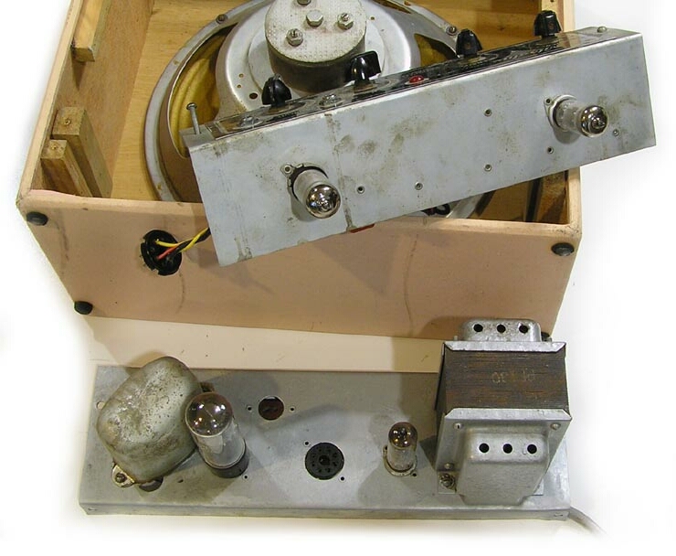
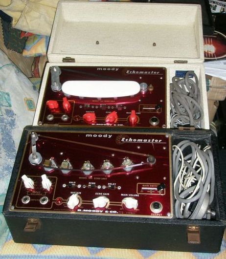
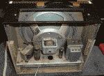
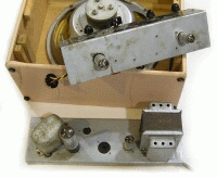
Daniel Cormick has sent this pic of a rare Moody tape echo unit.
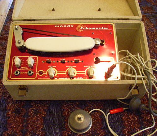
See also tapeecho article.
New: 21/1/08
Grant Wills has come up with a circuit tracing for a 40 watter.
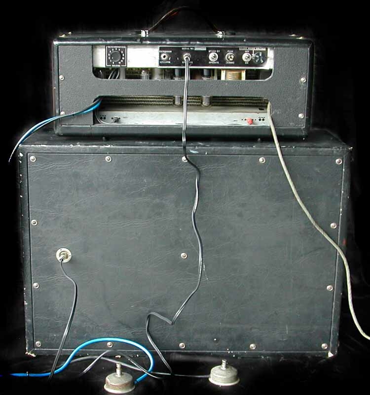
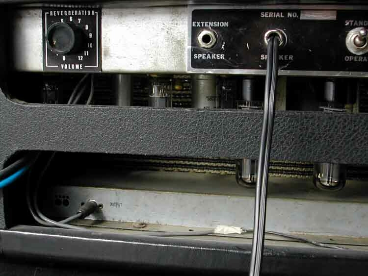
Authentic Hair stickers, retrofit external speaker socket, selectable mains voltages
from Miniwatt Digest source: Peter G Field
The four-page April 1964 Miniwatt Digest article including discussion, circuit, metalwork, and response curves in a zip file.
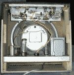
This is the circuit of the power supply and power amplifier portion of a two-unit arrangement, the other being the control unit and preamp.
This once common arrangement allowed the front panel and the heavy transformers to be placed in the case with greater flexibility than a single-chassis unit.
While this worked very well in radiograms and the like, allowing some design freedom around the front panel controls despite the clunky components of the time, placing the power amp valves in the bottom of a combo case exposed them to breakage.
Even with the Fender-style chassis which places the valves in the top of the case I still sometimes get the occasional power valve broken by the mains plug as the mains lead is reefed out or thrown into the back in the process of setup or packup.
A 5-pin connector takes heater and HT to the control unit and brings in the signal post volume.
The pentode section of a 6BL8 is used as the voltage amplifier and feedback summer.
The triode section is used as a split load phase inverter.
This drives a fixed-bias pair of 6CA7/EL34's delivering 60 watts to a nominal 8 ohm load.
The power supply consists of two voltage doublers, one for the output stage HT alone, the other for screen and preamps. Both are choke filtered.
The following spec sheet was in my Moody notes from the 60's but I have no idea how I came by it. I certainly wasn't measuring intermodulation distortion on guitar amps at that time.
Power transformer: Ferguson PF 2085
227 Vrms 200mA DC
177 Vrms 100mA DC
 47 Vrms
2 x 6.3 Vac ct @ 3A

Output transformer: Ferguson OP/480
Primary 4000 ohms
Secondary 8 ohms

Filter chokes: Ferguson FL-285
		No-sig	Full sig
Ep sup		570V	510V
Ip		2x33mA	2x10³mA
Eg2sup		465V	430v
Eg2		455V	380V
Ig2		2x4.2mA	2x21mA
Eg1		-38.5V	-37.0V

Performance spec:
Rated power out		60W
THD (60W 1kHz)		0.45%
Intermod (60Hz/10kHz)	2.1%
Sensitivity (60W)	530mV

Frequency response (60W)
	flat 44hz - 8kHz
	-3dB 28Hz - 36kHz
Feedback = 17.8dB
Hum and noise (to 60W) = -75dB
Class of operation: B1
Compare the class of operation, B1, to the complaints of overheating below. It's possible some have tried to reduce distortion by reducing the bias for class-AB1 operation, over dissipating the anodes in the process.
New: 8/4/07
Source: thanks to the efforts of Ian MillerGIF's 30-50kb each.
Normal preamp channel circuit.
Reverb/Tremolo preamp channel circuit. Errata: 27/09/2013 - the join of the three 220k resistors in the tremolo high pass filter, far right, should be grounded. Thanks to Jeremy Shaw.Power amplifier circuit.
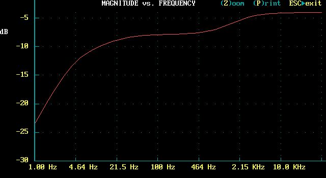
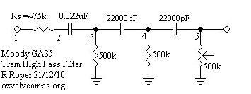
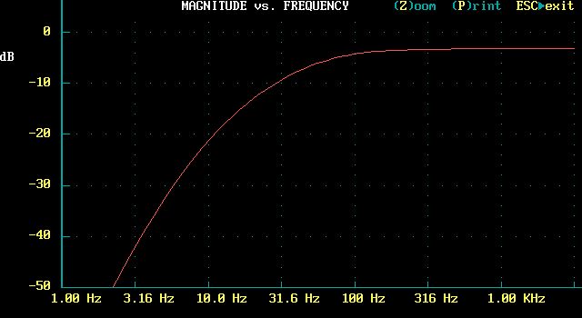
Trem High Pass Filter response - only -10dB at 10Hz.
Power supply circuit.
Reverb drive and recovery circuit.
Tremolo oscillator and buffer circuit.
New: 3/7/06
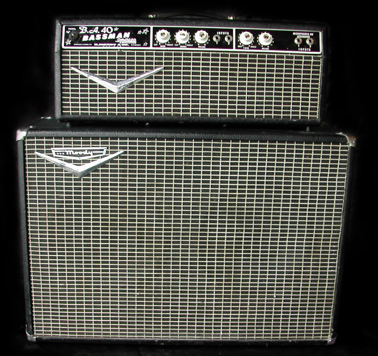
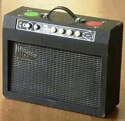
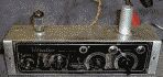
“Manufactured for Ultratone, Sydney”.
What's an Ultratone doing on the Moody page? Well the first clue is on the front panel “Manufactured for”. The second clue is the reverb control knob on the back. If you compare the position and hardware to the Moody above you will see that it is in the same position and uses the same escutchon and knob. This is a dead givaway that both amps were constructed in the same workshop.
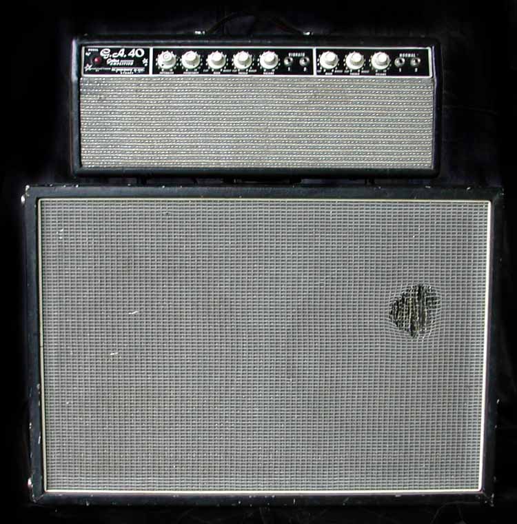
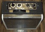
If you want to re-create this missing cabinet for a Moody head, or you're looking for simple but developed design 2x12 guitar cab, you will find the construction drawings of this cabinet here (30kb gif, measurements are in furlongs and cubits ;). The original was flakeboard but I'd use ply for a more durable result.
All cabinets of this vintage used black “cloth-backed vinyl” for covering. Root-balling cloth from your local plant nursery makes a great, cheap, substitute. As for the grill cloth and flying V logo, you'll have to improvise.
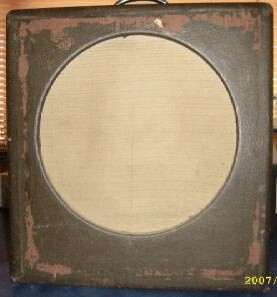
The pic above shows the downside of speaker fabric after it has been torn by something like a mike stand in transit. These days I follow the herd and use steel grill speaker protectors and no cloth. These look industrial ugly, but are cheap and give the speaker much better protection than cloth.
If you do use a synthetic grill cloth the trick is to first attach it evenly but comfortably slack. Then you slowly paint it with heat, say from a one-bar electric radiator from about a foot range, and the fabric shrinks. Done carefully the result is drum-tight. The edge D-bead holds the fabric clear of the baffle to avoid slap when the speaker drives.
If you overheat one spot it will overshrink and distort the fabric pattern, and if you really overdo it it will suddenly rip along one side, and you have to start again. Initial evenness and aligning the fabric pattern with the edge of the baffle is important to the final look.
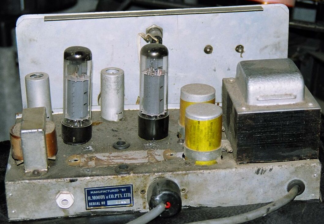
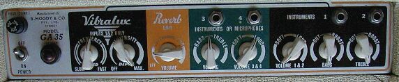
Pair of EL34's (says 6CA7 on the chassis)
cathode bias, with a 130 Ohm 10W cathode resistor
390VDC on the plates
about 30 - 35W of clean 1kHz sinewave into 8 Ohm resistive load.
EL34's are idling at something like 75mA!
Switching the voltage selector to the 250V tap
 cools things off to where the o/p's are idling
 right at about 25W with around 350VDC on the plates
Output is down to 20W at this point.

Source: Stuart Kent Sat Feb 1, 2003, ANZamps

---

Price Paid: $200AU used
Two channels, both with two inputs,
one channel normal, one channel vibrato.
Reverb unit
Two footswitches, one for vibrato and one for reverb.
All knobs go to 12,
 except for bass and treble which go from cut6 to boost6.
It's pretty much a straight copy of a Fender twin reverb circa 50's.

Source: Harmony-Central

---

Price Paid: $A5
Made in Sydney early 60s
2 channel
company went bust 35 years ago

I have circuit for reverb.

Submitted by G BOUCHER at 03/09/2002
Source: Harmony-Central

---

Price Paid: (150 Aust dollars) used
EL34's
Bias modified - overheated and burned the valves out

Submitted by TONY at 12/21/2001 15:38
Source: Harmony-Central

---

Price Paid: 270 (GBP) used

I would say it was a 60's amp, from it's design and circuit.
There are 4 inputs on the front
2 for guitar and
2 for accordion
2 speaker outputs on the back
2 EL34's form the power stage
Accordion chanels are DIRTY if you like traditional pre amp distortion (12ax7s)
Channel one is darker than 2

Submitted by Ant Lockyer
Source: Harmony-Central

---

Price Paid: FREE (found in gutter (YES!))
resembles the Fender Bandmaster.
2 inputs with seperate controls.
 One is for a standard instrument input
 with a gain, bass & treble control.
The other is for a mic or accordion!
input with a gain and tone control.
the controls go to 12
2 x EL34 in the power stage
12AX7 on the input.
6BQ6 (?).
assume the rectifier is solid state.
Built:  60s and early 70s

Looks a lot like a black face Fender with silver grillcloth.
The knobs are chicken head
Cosmic looking stars stencilled onto the front panel.
Big V logo on the grill

Submitted by Leigh Ivin at 05/09/2001
Source: Harmony-Central
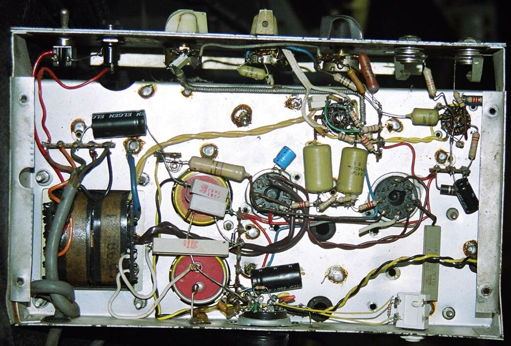
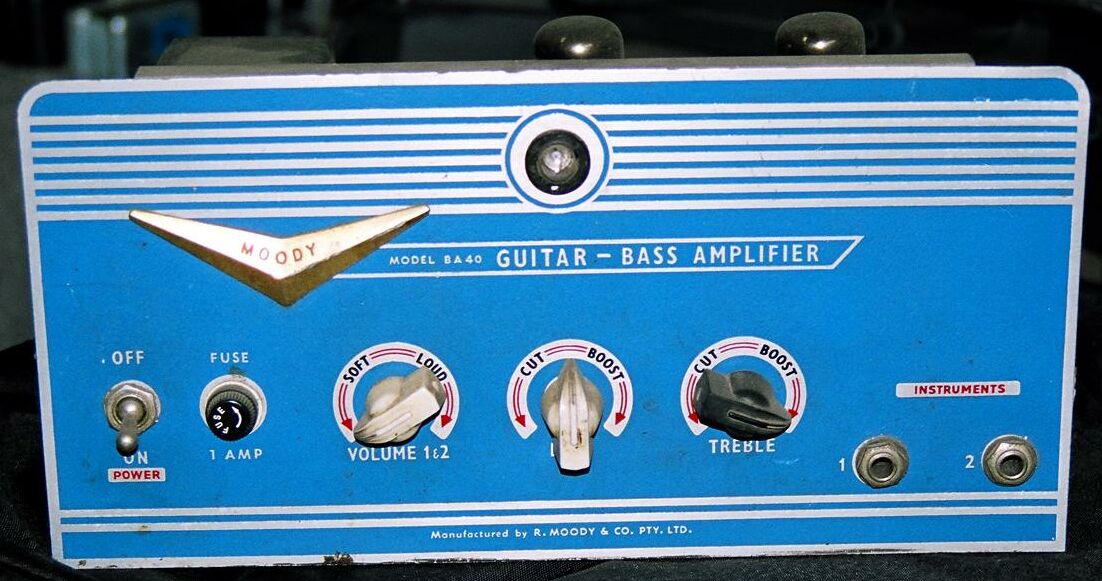
Brad has provided the following, re-constructed scan of the factory schematic that came with his Amp. Thx.
The first 12AX7 is used to amplify and anode mix the two input channels into a passive 2-way tone control network, then volume control.
This is followed by a 6BL8 pentode voltage amplifier and feedback summer, and triode split load phase inverter.
This drives a pair of 6CA7/EL34's using cathode bias, rather than fixed bias, for 40 watts out. Tranny shows two secondary taps.
The power supply is a solid-state voltage doubler with series inductor filtering.
There also appears to be a high-tension interlock on the speaker connector to prevent operation without a load.
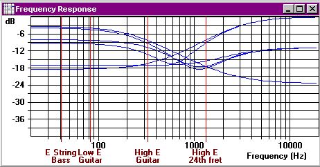
Approximate tone control response.BA40
Click for full size 125kb jpg |
Click for full size 131kb jpg |
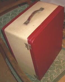
Source: Ian Rumbold
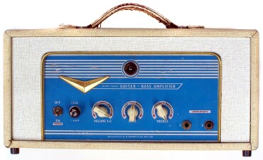
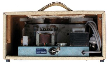
In an original blond case;
New: 8/4/07
![]()
Nice draft of the GA-35 circuit. (40kb gif)
Enlargements of above:
preamp,
power amp/PSU.
Source: with thanks to Mark Parsons
Update: 21/12/10
Characteristic of the tremolo High Pass Filter.
Update: 13/1/07

Source: Gary Kurzer
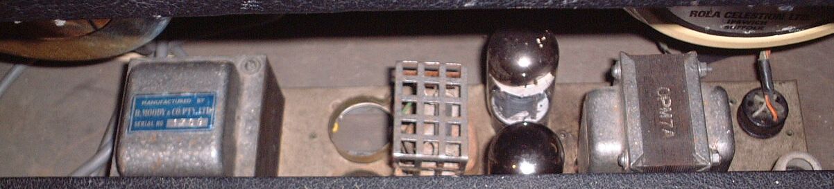
Serial: 1758(?)
OPT: OPM7A
This is a Ferguson unit rated at 15 watts.
[13/1/07] Note: the OPM7A in this unit is now confirmed to be a replacement, the original being a Ferguson OP429. I don't have the data on this one, but I'll guess that it's similar to their OP499/8.4, 60Watt, 4Kp-p to 8.4ohm, “suit 6CA7/EL34”, 2.5x4.5x3 inch.
Thanks to Gary Kurzer and Evan Lorden.
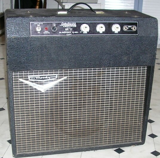
Source: Mark Chandler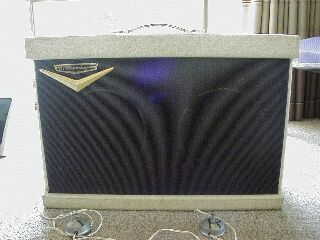
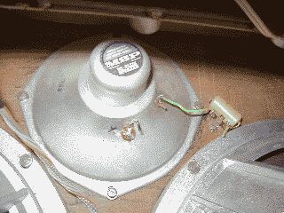
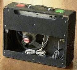
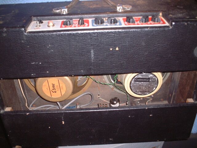
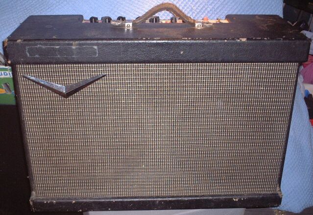
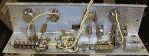
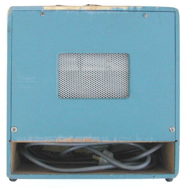
Gee, yet another Moody with the tweeter disconnected.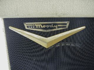
Note the HT sag resistor under cage
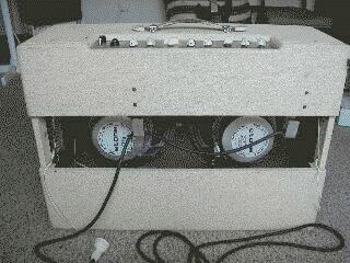
Price Paid: 150 (Australian) used
2 x 12-inch 100 watt four tube combo plus a tweeter.
Cream vinyl finish.
Two guitar & two Instrument/mike inputs
each set of two with balance & tone controls.
1 channel only (very clean but with some warmth).
Two footswitches one for Vibrolux tremelo
one for reverb

Submitted by Adrian Bell
Source: Harmony-Central
This “100 watts” is of course input power, output being 35 watts. “Four tube” being the total valve count.
New: 8/4/07
Power amp circuit (mud-map - 22kb gif)
Source: Robert D'Alessandro
Price Paid: N/A used
Built: December 1967 (manufacturing date on the power transformer)
Combo Amp.
Same dimensions as my Fender Twin 65 Reissue.
1 x 12-inch speaker
Volume, Treble and bass controls.
Two inputs labelled 1 an 2.
Finished in black vinyl - very thin and unavailable now.
Uses EL84's
valve rectifier.
6BA7 and 12AX7 in preamp.
Around 15 watts.
It hadn't worked since 1974.

Submitted by Jason Ferridge 03/30/2000
Source: Harmony-Central
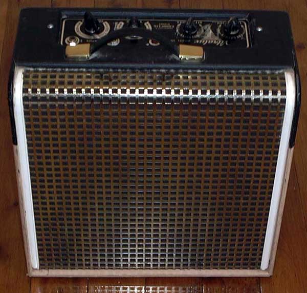
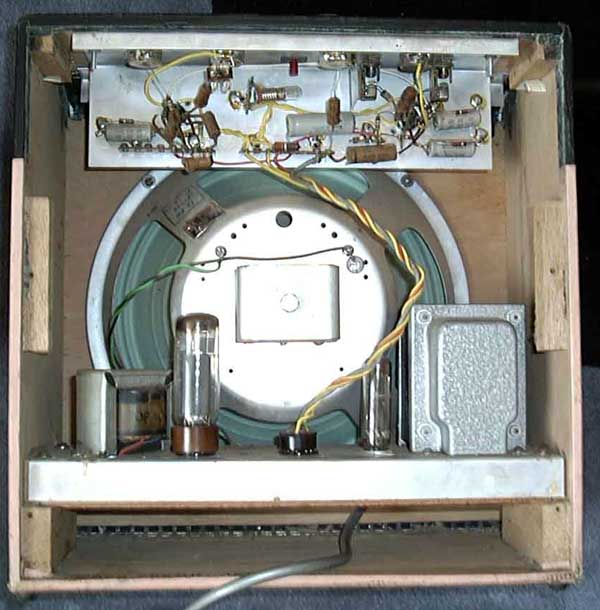
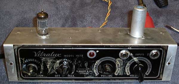
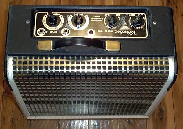
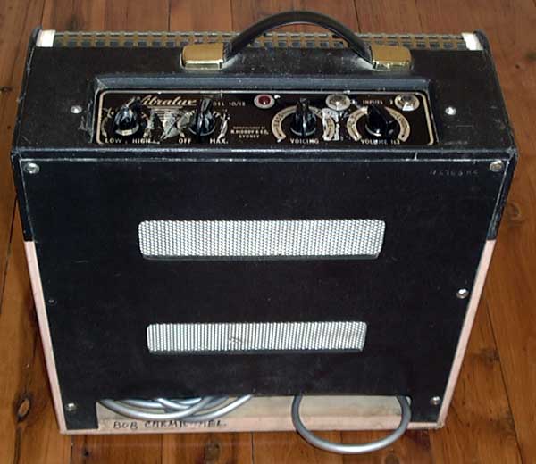
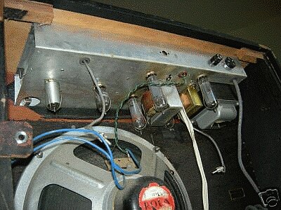
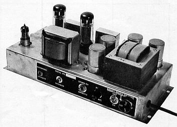
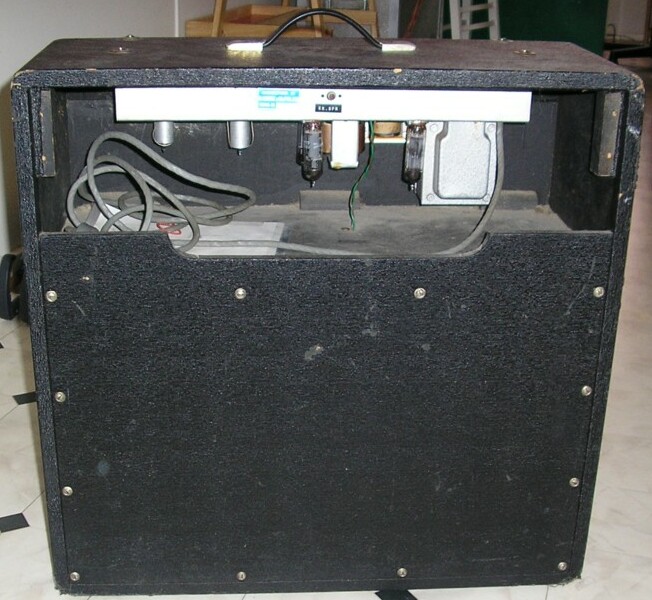
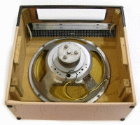
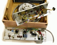
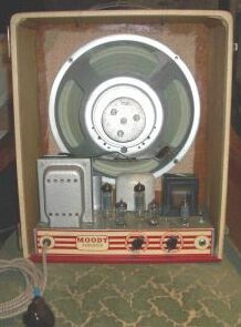
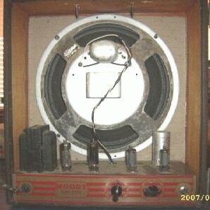
Price Paid: 155 (Australian) used Built: Output transformer is dated 8/60, August 1960. Gold look square grill front. Very thin light pink and black vinyl type covering. Controls are at the top/back (like Old Fender Champ / Bassman style). Construction - 6mm ply 340mm wide x 350 high x 150mm deep. The power transformer fits within the gaps in the speaker basket. Power section at the base of the amp, pre-amp section with a 12AX7 for the preamp and 12AX7 for the vibrato effect. It has 2 x 6.5mm jack inputs. Volume (Soft - Loud) Voicing (Tone) Intensity and Speed (Vibrato) Red Pilot light. No on off switch, no fuse. Tone control appears never to have been wired up properly we've got it working for the first time in over 43 years. Single ended EL34 (6CA7) Class A amp. Has a 6CA4 Rectifier tube. Very unusual configuration. EL34 runs pretty hot Submitted by Colin 05/03/2004 05:07 Source: Harmony-Central---Vibralux model 10/12.
Built: Aug 1960
Click on image for full size, all less than 50kb.

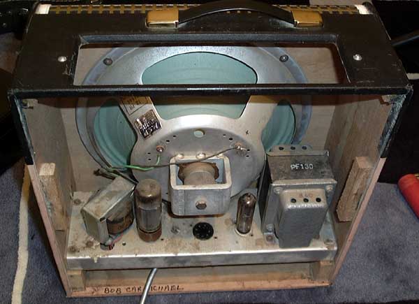
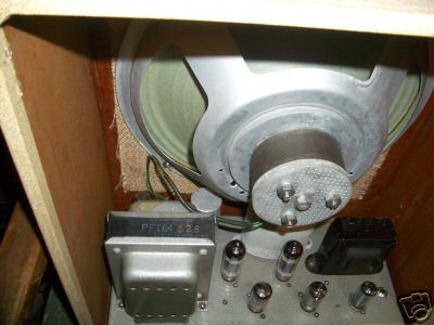
 I assume that the 12 refers to 12-inch speaker, the 10 to 10 watts output. Amp has seperate power and pre-amp chassis in one cabinet, connected by a octal plug. One 12AX7 provides two stages of gain, simple high-cut tone control. The other 12AX7 is a vibrato oscillator (phase shift type) driving a cathode follower. The cathode follower changes the bias on the first stage. The power amp uses one 6CA4 rectifier and one EL34 output tube. It runs really hot, 325 volts on the plate, 110 mA cathode current. Really small case no fuse and no switch. Speaker is MSP 12PR Power transformer is Ferguson PF140. Output transformer is Ferguson type OT40?. Built: Date code on power transformer is 860 (August 1960) David Crittle Thu Apr 29, 2004 Source: ANZamps
I'll bet it runs hot, 36 watts anode dissipation when the EL34 rated maximum is 25 watts.
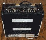
Two-tone pink and grey leatherette - can you believe it? Memories of your kitchen chrome and vinyl kitchen chairs in '63, or your EK Holden...
Grouse single-ended 6V6 tone. Valve rectifier, and the most delightful tremolo you could wish for! Circuitry has been gone over, with new caps and resistors fitted throughout. The original yellow-cone Alnico speaker sounds as good as the day it was made back in '63.
$795AUD plus shipping costs (Jan '06)
Source: Neil Rote, Grouse Guitars.
Here are some more Vibralux pics at Retrovox: (remote links, open in new window) vibralux_1 vibralux_2 vibralux_3 vibralux_4 vibralux_5 vibralux_6 vibralux_7 vibralux_8


Source: Neil Rote, Grouse Guitars.
This little (32cm H x 30cm W x 16.5cm D, and only 4kg) beauty is incredible. Totally original in every respect. Very low power, but TONE, TONE and more single-ended TONE! Speaker is the original Sydney-made “MSP Hi-flux” 6” x 9”. Truly qualifies as GROUSE. The power transformer code indicates a 1961 build date. The valves used are a 6V4 rectifier, 12AX7 preamp and 6M5 power pentode output.
Collectable and usable, either as a practice amp or for recording.
$650AUD plus shipping costs. (Jan '06)
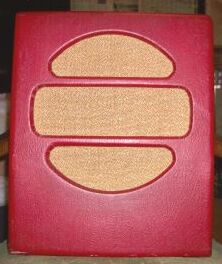
23/08/05

Serial: 526
Output tubes  2 6BQ5 (EL84) Sovtek
5Y3 rectifier
1  6AU6
1  12AU7
1  EF86
2  inputs
  1  runs  EF86 (HI GAIN) aka VOX
  Other runs 6AU6 not as loud
Art deco looks good in any loungeroom. Burgundy thin cloth type covering and cream (has nice patina bit a dirt ) and it sounds better than it looks (serious filth). Has had small tonal mod! This configuration was used on VOX AC 15 watt amps (2 6BQ5 EF86) This particular amp was used by a lap steel player around melb in the 1950s.
New: 23/8/07
Source: Jason Liebeknecht
If you have any information about these amplifiers please see How to Submit.
|
|