|
http://www.ozvalveamps.org/ava100/ava100pa.html | Created: 18/10/06 | Last update:
10:32 19/03/09
<<< OzValveAmps |
Design of a valve guitar amp push-pull output stage.
![]()
![]() Caution: AVA100-Series is a work in progress and as such may contain significant errors.
Caution: AVA100-Series is a work in progress and as such may contain significant errors.
Edit: 15/08/2008, minor edit: 18/03/2009, markup edits: 02/08/2015
Just so we know what we are talking about, here is the circuit fragment of the output stage we are going to be considering...
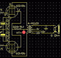
There are several different possible starting points when you decide to build an output stage, the most common being to start off with the desired power output and lists of output valves and output transformers.
In this case the output transformer, and strictly the load impedance, is a given at 8k ohms plate-to-plate and therefore must be our starting point.
(Note that I use the British “anode” and American “plate” interchangably to mean the same thing. This is a result of being a tech in Australia with a historic foot in each camp.)
The output stage is the only stage that has to deliver power (watts), that is current as well as voltage, as compared to earlier stages that only have to deliver voltage gain (Av). (“gain”? See More Out Than In?)
Because of this, and the inherent high source impedance of valves, the most efficient transfer of power is obtained when the output stage is transformer-coupled to the speaker.
This output transformer is quite similar in concept to a mechanical gearbox which couples a high-revving, low-torque valve engine to a low-rev, high torque loudspeaker load.
Drawing a graphical loadline helps a lot in getting this gearbox ratio or impedance match right for the particular valves.
Loadlines
A loadline is a line drawn on the graph of the valve anode characteristic found in the valve datasheets. It represents all the possible combinations of plate voltage and current for one particular set of conditions.
The loadline is anchored at a HT voltage Vsupply, flatter lines represent higher load resistances (less current), while steeper lines represent lower resistance loads (more current).
Looking at the 6GW8 data sheets there are two sets of operating conditions given, one for 250 volt supply and the other for 300 volt supply. These are major guideposts and a reality check against whatever we come up with.
With the given load impedances at 8.2Kp-p for 10 watts out and 9.1Kp-p for 13.5 watts out, these are pretty close to the 8.0Kp-p 100-volt-line trannies that are available.
But since their 9.1K is a bit different to the 8K we've got, and we are running near the valve limits, we will look first at their conditions, then at how our intended conditions compare.
The first major constraint we have to deal with is the power dissipation limit for the anode. For a 6GW8 pentode this is 9 watts.
In the following graphs the anode voltage in volts runs along the bottom or x-axis of the graph, and the anode current in milliamps runs up the vertical or y-axis.
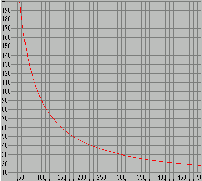
Anode power limit - Ea x Ia = 9 wattsSince the anode power is the product of the anode voltage Ea and the anode current Ia we can draw a curve that represents Ea x Ia = 9 watts. This is coloured red here because if you operate above it your anodes will get a cheery orange glow (just before they melt). So we don't want to operate above this line.
This is the elemental circuit we are initially dealing with, simply the valve in series with the load, across the supply. In the output stage the load is one half of the output transformer primary.
Elemental circuit
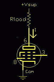
There are also two voltage drops that subtract from the available supply voltage, the cathode resistor if used, and the saturation voltage of the valve, both of which we will deal with later.
So let's have a look at what the loadline for their specified conditions looks like...
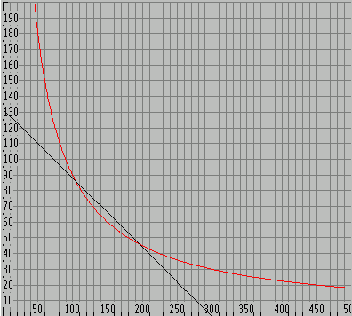
Vsup = 300V, RL = 9.1kp-pThis is a line representing the load resistance drawn between the two extreme conditions from cut-off (the bottom axis) to full conduction (the left vertical axis).
We start with the supply voltage, here 300 volts, on the bottom scale. This will be the anode voltage when the valve is cut-off, open circuit, and not drawing any current.
The saturated or full-on current is simply found (to a first approximation) by Ohm's Law from the supply voltage and load resistance, I = E / R.
Note: that in the case of a transformer-coupled push-pull stage, such as this, the impedance of one side (half) of the output transformer is one quarter of the plate-to-plate value. We are taking only half the total transformer turns, so we only have one quarter of the total plate-to-plate impedance, thus 8kp-p looks like a 2k load to each valve.
The datasheet load is 9.1Kp-p which gives 9.1 / 4 = 2.275K seen by each anode.
Again from Ohm's Law the current is Ia(max) = 300V / 2.275K = 132mA. (ignoring cathode and saturation drops)
Now we can draw their loadline for 9.1Kp-p (in black) from 300 volts to 132 milliamps.
Notice that in this simplified approximation it crosses a bit above our red 9 watt limit. We will assume that when the real valve saturation voltage is accounted for this will actually just graze the 9 watt line. So as long as our trial loadlines stay below their black loadline we will be okay.
Repeating this process for the 8kp-p transformer we can compare by plotting its load line (in yellow).
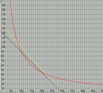
Vsup = 300V, RL = 9.1kp-p (black), RL = 8kp-p (yellow)As we can see, and should expect since our load is smaller than theirs, our 8k loadline bites even deeper into the forbidden hot zone above the 9 watt line than their 9.1k loadline, so we can assume that this proposed loadline will be starting to seriously strain the friendship.
This is not good. The most obvious thing to do is move our line to the left.
Since the gradient (slope) for a given load value is fixed, all loadlines for a given load will be in parallel, so we can therefore move our loadline bodily to the left and out of trouble by reducing the supply voltage.
We can simply make a guess (or estimate), or we can calculate. Since it can be shown [*] that the peak power point is at the half voltage point, and the resistance of the valve is (approximately) equal to the load resistance we can use the 9 watt power in our 2k load to find the maximum safe supply voltage.
[* Detail; this is called the Maximum Power Theorem or Maximum Power Transfer Theorem]
Since P = E2 / R we can transpose to find E = sqroot (P x R)...
[ P = E2 / R ... PR = E2 ... E = root(PR) ]
E = sqroot (9 x 2k) = 134 volts (x2 gives Vsupply = 268V)
I made a guess at 275 volts.
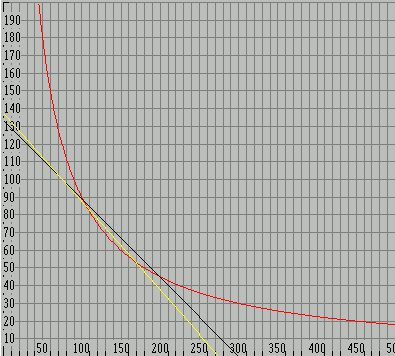
(black) Vsup = 300V, RL = 9.1kp-p
(yellow) Vsup = 268V, RL = 8kp-p
Compare this with the graph aboveSo here is our new simplified 8kp-p load with a 268 volt supply (yellow) which we can see now overlays the original 9.1k (black 2.275k) line, but rotated slightly clockwise to represent 8k (2.0k).
We have discovered that for these valves, driving this tranny, we have to be a bit careful about the actual HT voltage.
The Real Thing
Now we introduce an actual anode characeristic from the valve data book, in this case Philips ECL86 (6GW8) curve for the next lowest screen voltage Vg2=250 volts (in this case they supply two, one for Vg2=300V and one for Vg2=250).
On the 250 volt curve we have superimposed our 8kp-p loadline which runs from the 275V supply voltage to the implied current of 132mA.
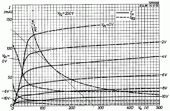
Now we can see a few things. Firstly at upper left we see the loadline crosses the Vg1=0 volts, or valve saturation point, at 50 volts and 110mA. This will be the saturated or full-on condition (clipping), and similar to the figure from the datasheet as a reality check. So at the peak point the current will be 110mA and the voltage across the valve will be 50 volts.
Distortion
If we look at the Vg=0 curve we can see it has a “knee” in it around 120mA and 60 volts. The lowest distortion is obtained when your loadline passes through this knee. Generally this condition cannot be met for maximum power output, and helps to explain why Hi-Fi's get less power, and guitar amps have more distortion, using the same valves - each is optimised for a different condition.
Here we are optimising for power in a given load, but if we were designing an era Hi-Fi we would investigate a lower HT and load to move our line up through the knee, if not UltraLinear screen connection (which we will also return to).
Linearity
Each of the anode curves is shown for a 2 volt increment of grid voltage, and casting our eye up and down our loadline we can see that it intersects each of these lines. We can see these intersections are more widely spaced in the middle than they are at the ends. This means distortion - compression of the signal peaks. The closer the grid line intersections bunch together on our loadline, the more the peaks are compressed.
It happens that the loadline for minimum distortion passes through the knee of the Vg = 0V curve. As we make the load higher we cross this line below the knee and the result is that the Vg lines are more compressed as we get towards saturation, which means the signal peaks will be somewhat flattened off (3rd harmonic distortion). It is quite possible to calculate the distortion, but for a guitar amp there isn't a lot of profit in it, and stuck with a choice of one load impedance there isn't much we can do about it either.
Starting at the supply voltage, 275 volts, we come straight up until we intersect with the 9 watt limit line, then read the current from the left - about 33mA which reality checks with the data sheet.
Or we can calculate it from P = I x E (transpose to) I = P / E.
[ P = I x E ... P / E = I ... I = P / E ]
9 watts / 275 volts = 32.7 mA. (against 32.5 mA from the datasheet)
By the way, these figures are written as they fell out of the process and not cooked up as a neat example, so we are looking for general agreement with the data sheet figures rather than spot-on accuracy.
Bias
We can now also get an idea of the bias voltage we are going to need.
We look at the characteristic graph again...

To find the actual Vg1 (bias) required we read this from the graph directly up along the 275 volt line too, but this is a bit tricky since we have to interpolate between the grid voltage lines as they only match the scale locally.
The only really accurate way is to measure the vertical distances by counting little squares and dividing -
(0.75+3+0.75) = 4.5 or 2.25div/V;
needed (0.25+2+0.75) = 3div.
Bias = 6 + (3/2.25)V = -7.33V
Resistance
So now we have 32.5 mA and need -7.4 volts of bias, so what is the cathode resistor required?
Again, out with Ohm's Law R = E / I or 7.5/0.0325 = 231 ohms. This is for each valve, or we can use a common cathode resistor of half that or 115 ohms. The obvious standard value is 120 ohms.
Incidentally we can find the resistor power required from P = E x I or
7.5 x 0.0325 = 244 mW, about a 1/4 watt actual.So a 1 watt or greater rating for each valve. A 5 watt ceramic wirewound would be the most logical choice.
Bypass
If we leave this resistance un-bypassed it will also introduce local AC negative feedback (NFB), reducing the AC gain of the stage.
If we decide to AC bypass the cathode resistor we need to place an electrolytic capacitor across it, but what value and rating?
The voltage is simple; it obviously must be higher than the bias voltage, but not too much higher or the cap won't form up to full capacity properly, so anything from about 9 volts up to about 20 volts working will do.
Cutoff frequency - Fc
The required value comes from the need to bypass the cathode resistance at the lowest frequency used, and that the effective resistance of the capacitor, its reactance Xc (in Ohms), changes with frequency.
As a rule of thumb, the -3dB or x0.707 point will be where the reactance of the capacitor, Xc, equals the bias resistor value.
Xc = 1 / 2 π f C
where:
Xc = reactance in ohms
f = frequency in Hertz
C = capacitance in faradsSince we actually want to know the capacitance, C, we transpose (multiply both sides by C, then divide b.s. by Xc; they swap places)...
C = 1 / 2 π f Xc
...select a low frequency cut-off, f = 100Hz, and substitute...
C = 1/2 π x 100Hz x 120ohms = 1.326e-5 or about 13 microfarads
A note on notation:
“1.326e-5” is a keyboardable form of scientific notation and means 1.326 x 10⁻⁵ or 13.26 x 10⁻⁶For bass guitar we need a lower cut-off so if we set f = 30Hz well below the bottom E on a bass, we get...
C = 1/2 π x 30 x 120 = 4.421e-5 or 44 microfarad.
Since we are looking at the -3dB points the signal will already be down at these frequencies, so if we want to remain reasonably flat and still deliver full output at that frequency we will actually need a by-pass that is quite a bit bigger - anywhere from 2 to 10 times depending on your tastes. This value is by no means critical, you just need to have enough.
OOPS! - Red Face Department
New 7/8/08
Ian Miller has been kind enough to write pointing out that my calculation of the required cathode bypass capacitor above contains a significant error by omission.
It was stated that the -3dB point will occur when the Xc of the bypass capacitor equals the cathode bias resistor value.
This is in fact not correct.
Looking into the cathode of a pentode you see an effective impedance of 1/gm, about 100 ohms for 6GW8, this impedance is in parallel with the cathode bias resistor.
For a pair of 6GW8 sharing a common 120 Ohm bias resistor the impedance looking into the cathodes will be Rk || 1/gm || 1/gm which amounts to about 35 ohms.
“||” = in parallel with
The -3dB point will occur when Xc = this 35 ohms.
This is a very common mistake when looking at cathode bypass capacitors whether it be for output tubes or small signal gain stages.
Looking into a pentodes cathode the impedance is approximately 1/gm.
Looking into a Triodes cathode the impedance is (RL + rp)/(mu + 1).
These impedances are always (AC wise) in parallel with the cathode bias resistor.
So the corrected (exact) values for 6GW8's in guitar and bass will be;
C = 1/2 π x 100Hz x 35ohms = 4.547e-5 or 45 microfarads
and;
C = 1/2 π x 30 x 35 = 151 microfarad.
Now we have calculated the exact values needed, but again with real-world components we need to select the nearest, or next highest, available value. In this case it would be 47uF for guitar, and 220uF for bass.
When dealing with electrolytic capacitors it is important to keep in mind that they are not precision components and their values are nominal and subject to a wide spread depending on manufacture, actual conditions of operation, and age; and therefore in bypassing situations such as this it is wise to err somewhat on the high side.
Ripple current
The other important property of this capacitor is its ripple current rating. This is (hopefully) found in the cap datasheet and needs to be at least twice the output stage idle current.
As ripple current is related to capacitor value, the final value selection may actually be driven by the available ripple current rating rather than just the required bypass low frequency cutoff. The voltage rating of this cap should be around 1.5 to 2 times the cathode voltage but because of the hot environment in a valve amp you will get the best cap life if the ripple current rating is well in excess of the actual current requirement.
As mentioned above the anode characteristic is shown in two graphs in the databook, one for a screen voltage Vg2 = 300 volts and the other for Vg2 = 250 volts.
Since we have found the required supply to be less than 300 volts it makes sense to use the 250 volt curves since the required voltage can be simply dropped from the main HT supply (rather than having a special 300 volt supply just for the screens).
As with the cathode we can either have a single common dropper resistor, or we can feed each screen via a resistor each.
We know we want to get rid of 275 - 250 = 25 volts. And we can see from the data that the screen current at full drive is about 10 mA per valve or 20 mA total. Again, applying Ohm's Law, to find what value of resistor will drop around 25 volts at a screen current of 10mA, R = E /I ...
R = 25 / 0.01 = 2500 ohms, or say 1.2k for a single resistor for both screens.
Ultra-linear
“Ultra-Linear” is another one of those terms like “Class-A” that sometimes gets thrown in to the conversation by people who don't know any better, trying to impress.
Ultra-Linear simply means that the screen grids are fed from taps between the HT feed and anodes on the output transformer primary, so the screen voltage varies somewhat in sympathy with the anode. This results in a mode of operation mid-way between triode connection (where the screen is simply connected to the anode), and pentode connection.
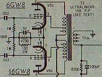
extract of PM103 circuit
Yet another guitar amp designed by an engineerAnother possibility presented by these transformers is that the primary also has taps either side of the centre tap. These are a logical point to connect each screen to experiment with ultra-linear connection.
A few points to note; firstly that U/L connection has been used in some guitar amps such as the Playmaster 102 and 103 (above), but not more generally as it reduces available output power, and guitarists are normally not that interested in having an amp with very low distortion.
The correct percentage tapping point varies depending on the valve type. EL36/6CA7's seems to like 46%, while I've seen KT88's on only 10%. So there is no assurance that the taps available will be suitable for proper U/L operation. This can be left to be investigated on the built prototype.
And lastly; that some resistance may still be needed anyway between each screen and its transformer tap to limit the idle power dissipation in the screen grids to less than the 1.8 watt limit.
Power output
The peak voltage swing available on the anode is Vsupply less the valve saturation voltage Vsat, 275 - 50 = 225 volts peak, or (divided by root(2)=1.414) 160 volts rms in the 2k ohm load.
P = E2/R = 1602/2000 = 12.6 watts
This looks pretty satisfactory, either on its own, or in a stereo pair.
With cathode bias the grid resistors are grounded to provide the ground reference for the grids, effectively now negative with respect to the cathode. The positive voltage on the cathode is the negative grid bias.
Normally in a Hi-Fi amp these would be kept at the spec value of 680k ohms each, but guitar amps have a special consideration - they are frequently operated under deliberate continual overdrive.
Under these conditions the pentode grids will be driven positive and grid rectification will result. The grid and cathode form a diode, and during overdrive this diode becomes forward biassed and conducts. This means that some of the voltage from the driver is rectified and stored on the input coupling capacitors.
This results in excess bias and the output stage “choking up” and going into a form of self-limiting. For this reason in guitar amps the output valve grid return resistors are as low as the preceeding driving stage can tolerate, allowing this excess bias charge to bleed away more rapidly, allowing the amp to recover proper bias operation more quickly. Driving this lower load resistance becomes a consideration for the preceeding stage driving it, in our case the phase inverter...
The triode section of the 6GW8 is basically half a 12AX7, so we can simply copy a phase inverter design that uses one.
Split load
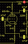
This is the most economical form and should provide the roughly 7 volts of drive required by the pentode grids without any problem. Its main attraction here is that it uses only one of the triode sections leaving the other free as a voltage amplifier stage.
The split-load PI is very similar to a normal 12AX7 triode stage except that the anode load is split half-and-half between the anode and cathode circuits. This produces an in-phase signal at the cathode and an inverted signal at the anode.
Again we can work from a typical operation condition given in the datasheet. This type of PI is basically a cathode follower so it only has a voltage gain a shade less than unity, meaning the signal at the grid input required for full output also need to be about 7 volts.
This arrangement also leaves the other triode available for some badly needed pre-PI voltage gain, 7 volts being a pretty poor sensitivity for full output.
Under the conditions given this voltage amp stage should have a gain of about x70, so the resulting main amp input sensitivity will be around 7 / 70 = 100 mV max. This leaves some excess gain if we want to introduce some overall NFB around the main amp later, but sensitive enough to be driven by most guitars, and certainly stompboxes.
There are other PI arrangements that can be employed using both available triodes, the balance Long Tailed Pair and the Unity Inverter types in particular.
dB - decibels
The main thing to remember about decibels is that they are not absolute, but a ratio or percentage, a way of expressing how many times one thing is with respect to another. Decibels are an easy way to express very large ratios, and to simply add up the gains and losses in a signal chain.
One light-second is 186,000 miles or 300,000 km, so one light-second is 105.39 dB(mile) or 109.54 dB(km). The ratio of a kilometer to a mile is about 4.1dB. So 105 + 4 = 109.
Negative Feedback
Yes or no, where, and how much?
There are a lot of arguments about NFB. This suggests that this is as much a matter of individual taste as electronic engineering, so you can leave it right out if you like the sound, but it is more conventional with a valve guitar amp to apply a small (by some Hi-Fi standards) amount of NFB, typically 6 to 12dB.
NFB does good things apart from reducing gain; it reduces the internal noise, widens bandwidth, reduces distortion, and lowers the output impedance.
These should all be desirable in a Hi-Fi amp, but in a guitar amp this normalisation can suppress the very “characteristic voice” that a guitarist is looking for.
Concept: feedback is measured by how much gain reduction it produces in the amplifier, in dB.
Minus-6dB is a fancy way of saying half voltage, so this is the amount of NFB that reduces the overall sensitivity of the amp by half, doubles the required voltage for full output. 12db means a quarter, so the sensitivity would be one-quarter.
You will often notice a small capacitor connected across the feedback series resistor (the one connected to the loudspeaker circuit). This is a high-frequency stabilty capacitor which is sometimes marked “SoT” for Select on Test because it depends on the actual output transformer used.
The phase relationship between the primary and secondary of the output transformer is pretty constant over the transformer bandwidth, but is subject to rotation above and below the rated working bandwidth.
At the high frequency end in particular there may be a large phase rotation while there is still significant gain in the NFB loop, and this may result in instability, parasitic supersonic oscillation, or outright high frequency oscillation.
If you have access to an oscilloscope you can drive the amplifier with a square wave and select the value of cap that gives the output with the squarest edges, no droop or overshoot. This depends a lot on the individual output transformer used, but is generally much less of an issue in guitar service and with low levels of NFB.
As noted above, if the bypasses on the output valve cathode resistors are omitted the stage will be subject to local NFB. If you want something between all or nothing then you can split the value of the cathode resistor and only bypass part of it to obtain the ratio of DC to AC NFB desired.
It's worth mentioning that a few amp builders used the NFB loop to provide what was generally called a “presence” control. Goldentone, Strauss and Moody were some that did this in some amps.
We have a choice of two trannies that will work in this output stage.
The smaller M1115 tranny is slightly cheaper and smaller, has an 8 ohm secondary, and will certainly work, but from experiments it seems this power rating is programme or peak, not RMS, so it's 15 watts is more like 10 watts rms.
This means that the amp will tend to limit on transformer saturation first, and the tranny will tend to get quite hot under overdrive.
The slightly larger M1120 is rated at 20 watts so we can assume 14 watts rms, just right for our expected 12.5 watts. It also offers three different speaker impedances, 4/8/16 ohms, which could be very flexable in practice.
For bass guitar use there is no choice - it must be the bigger M1120 for its better low frequency performance.
So we now have some values as a starting point that should produce a reasonable small amplifier:
AVA100-6GW8 PM103-6GW8 AVA101-1-6BQ5 Rload 8Kp-p (given) 10Kp-p 8kp-p Pdis 2x 9 watts (given) 2x 7W Pout 12.5 watts 2x 12W 16W Vsupply 275V 310V 310V Vg2 250 volts (given) 310 volts (U/L) 290V Rg2 1.2k for both nil - U/L 2k2 for both Rk 120r both 145r both 150r both Ck 50uF/12V or more 50uF 470uF/25V Open loop sens 100 mV
I have found that some people have difficulty with the concept of stage gain.
“How can you get more out than you put in?”
Well you can't, and strictly speaking the input signal voltage doesn't actually pass through the active device, in this case a valve, to the output at all. It only controls what happens there.
And it is well-named as a valve because it acts as a controlled valve or tap in another circuit. This circuit consists of the load, the valve, and the power supply. The input voltage (or current in a transistor) controls the flow in the main circuit, just as your hand can control a lot of force by turning a tap, switching a switch, or turning a volume control or light dimmer.
So the power required for a stage to have gain actually comes from the mains via the power supply.
No laws of physics were broken in the designing of this amplifer.
|
|