As an electronics technician specialising in design I am constantly amazed at what naturalists get up to, such as super-gluing tiny tracking transmitters to the backs of Fairy penguins.(*)
For reasons that remain obscure, an ecologist friend decided that it would be interesting to listen to rivers. He didn't mean a soothing soundscape, but what sounds where happening in the river itself.
Everybody has heard whalesong but seems all sort of aquatic species make all sorts of noises.
Apart from the sounds of them swimming and foraging or hunting which can be used to identify species and track movements, we are finding some surprises as fish "converse".
After a few hopeful experiments sticking a cheap dynamic microphone wrapped in a plastic bag into a river I was asked to consider the problem.
A bit of a think and a dig in the junkbox came up with some piezo(*) elements. One was selected of the same diameter as popular 'poly-pipe' farm plumbing fittings.
The idea was to produce a waterproof container with the piezo blocking one end. A reducer and water-tight cable gland fitted at the other end. This gland fitting alone was the most expensive component.
A piezo element is not a particularly good microphone, having a number of mechanical resonances and a very high output impedance, but the end result is a satisfactory and very robust microphone waterproof to at least 10m/30ft.
Circuit

The main electronic problem is the very high impedance of the piezo element. To the amplifier it looks like a signal in series with a 10,000pF capacitor.
Conventional amplifier arrangements would excessively load the output, particularly at lower frequencies.
The piezo is a high output element and if knocked, something almost certain in this application, it can produce volts of output. Some protection is required both for the amplifier and the operators' ears.
The distance from microphone to the recorder in the observers riverside hide may be many metres long, bringing into consideration driving the cable by the microphone.
Making the microphone pod active by placing an amplifier in it meets these problems.
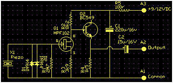
The output of the piezo is clamped by back-to-back diodes right across it. This limits the peak voltage at the amplifier input to around +/-650mV.
Resistor R1 is a critical component. As the load resistor for the piezo it has a major influence on low frequency operation and really needs to be matched to the piezo element used.
If it is too low the microphone will lack bass, if too high will have a bass peak. Since piezo's were once a popular record pickup I looked at amplifier practice of the period and found that the use of a 2M7 load was almost universal.
Looking at it another way the element was driven via a largish resistor from the audio signal generator and the voltage across the element measured at several frequencies on the oscilloscope.
This is complicated by the mechanical resonances so you just have to find representative average points. For this sample the result was around 10,000pF.
Load resistors were tried from 1M to 10M and listening tests confirm 2M7 as about right.
The rest of the amplifier consists of a FET directly coupled to a transistor emitter follower to drive the cable.
The DC biasing Q-point aims to have the emitter of Q2 around half the supply voltage. The main difficulty is the very wide spread of parameters for Q1 the MPF102/2N3819 FET.
The maximum signal swing at the output is only a couple of volts so it doesn't have to be exactly centred, only that far from either rail. If it needs to be tweeked change R3.
If it's wildly off and there is no fault, try a different FET or even a different type.
The FET is a static-insensitive junction gate type and presents almost no loading to the piezo element. It has a voltage amplification factor of about 2x and a moderately low output impedance.
This is coupled to an emitter follower with a very low output impedance, meaning it can drive the high capacitance of a long cable without suffering high frequency losses.
The cable used is an 8mm high quality twin screened mike cable with a very heavy duty covering. Power is sent to the unit via the screen and one inner, while the signal returns via the screen and the other inner conductor.
Operation
While this circuit provides a little voltage gain, its main role is to transform the high impedance of the piezo to low impedance to drive the cable.
Layout

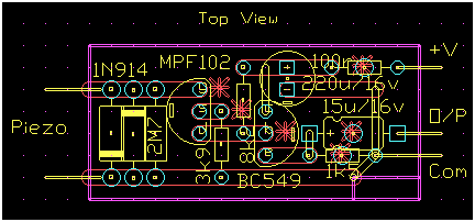
Circuit layout isn't critical apart from making sure the piezo-to-gate isn't exposed to leakage. One way of avoiding this is to avoid the board and wire this part aero-board style. If you get a sound like frying eggs and popcorn you've got surface leakage.
A way of locating this is to bake the circuit under a desk lamp, then gently blow on suspect areas through a tube like the body of a ball-point pen while listening to the output.
Once the offending area is found let it bake dry and silent then paint the area with a dab of Silastic to keep it dry.
Construction
Original construction was on strip-board and the track cuts are shown as (*) on the layout.
Before final assembly a layer of kitchen cling-wrap was placed over the outside face of the piezo to prevent actual contact between the metal disk of the piezo and the water.
Testing
Check that the emitter voltage of Q2 is between about one-third and two-thirds of the supply voltage. Tweek with R3 if required.
The most important aspect is making sure it's all watertight before you plonk it in water.
Packaging
Black polypipe fittings present themselves as a cheap starting point for a waterproof enclosure.
Sidebars
(*) If you think gluing transmitters to penguins is cruel please understand that the study was in response to mass penguin deaths.
Be assured that the world of radio tracking is well aware that any transmitter must not change the behavior of the animal or the whole object of the study is defeated.
Huge work goes into developing ultra light transmitters and methods of attachment that are fail safe for the animal.
In the case of the penguins they were as difficult to attach to as a greased pig. Most of the transmitters could be expected to simply drop off. The backstop was when the birds moult any surviving unit would be shed.
What were they dying of? Starvation. We are simply out-competing them for fish.
(*) Piezo. Some crystals, Quartz particularly, and some man-made ceramics exhibit the piezo-electric effect. If they are subject to stress or compression a voltage appears on the opposite faces of the crystal. Similarly an applied voltage causes flexture of the crystal.
This forms the basis of 'crystal' record playing cartrages and microphones, both now effectively obsolete, and still popular piezo tweeters.