Layout
Construction
Testing
Packaging
MIDI (“Middy”) - Musical Instrument Digital Interface - is a simple and reliable way to connect keyboard, computer, and rack synths together.
It is a serial protocol like a computer COM port, but unlike a COM port it is a current loop rather than a voltage level.
The bit rate is around 32kBPS which looks sick compared to USB or Firewire.
And it is.
But MIDI was designed to connect a few devices, not drive an entire time-critical studio.
It still does that, and well enough to do it on-stage. Being slower is also less demanding on cable quality and allows greater length.
The standard MIDI connector is a 5-pin 180 degree DIN, socket on equipment, plug on cable, and only uses two pins.
The connection is polarity sensitive.
Since a standard sized DIN socket won't quite fit the standard computer card rear connector strip, Creative used the joystick port connector, a D-15 male, to carry their MIDI logic levels.
So the most popular MIDI device is also the only one that has a MIDI connector that isn't, and MIDI signals that aren't.
The phrase “islands of automation” comes to mind. May emus kick down their dunny.
Anyway, if Necessity is the Mother of Invention, then incompatability is a kick in its bum.
The design presented here is very standard, but features data tell-tales.
A MIDI-box has to do three things:
- convert D-15 to 5pin/180° DIN sockets
- convert between logic and current loop
- electrically isolate the incoming current loop
This last point is very important but sometimes ignored in articles and even in commercial cable MIDI “adaptors”.
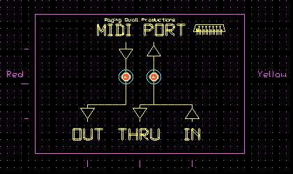
MIDI sockets are identical but come in three flavors:
- Out - keys to remote synth, computer, etc.
- In - incoming to noise-maker.
- Thru - a direct regeneration of In for daisy-chaining.
The most basic MIDI device such as keyboard or pedal clavier has only one Out socket.
Cheaper synths have two, and In and Out.
The standard kit is In, Out and Thru.
Note that unlike RS-232 you need a cable for each direction.
The box described here solves the connector, level, and isolation problems, and also provides signal indications, all without an external power supply.
Circuit
The circuit is in two sections, the upper section incoming to the computer soundcard, and the lower section the outgoing.
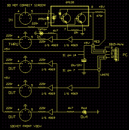
The MIDI leaves the soundcard as a logic level on pin 12. One of the hex inverters buffer this and drives three other inverters and the Out mimic LED.
These three inverters provide three isolated drives for three Out's.
On the In side it is a vital detail that the screen of the incoming cable is not connected, to prevent earth loops.
The incoming signal causes the LED inside the 6N138 opto-coupler to flash and the two internal transistors detect and amplify the signal.
The optocoupler allows the signal to pass without making any direct electrical connection.
The signal passes from the opto to pin 15, the incoming data on the soundcard connector.
It is also taken to an inverter that buffers it and drives the In mimic LED, then another inverter as the Thru output driver.
5 volt power is derived from the joystick/MIDI connector.
Layout
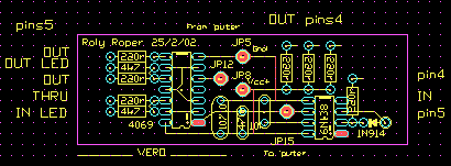
JP5, 8, 12 and 15 go to these pins on the soundcard connector.
Layout is non-critical apart from maintaining isolation of the opto input side.
Construction
These have been constructed using both dab and strip board.
Testing
Required:
- A computer with soundcard
- suitable software,
- a .MID file to play,
- a MIDI instrument,
- and a MIDI cable or two.
Note:
If you haven't already, verify that your system will play .MID files back through its own speakers. If not you must get that under control first.
The internal computer MIDI output channel will need to be redirected from the soundcards' internal MIDI synth to the external channel. This generally can be done from within your sound software.
- Connect the MIDI box to the computer. The LEDs should not light.
- Play the .MID file. The Out mimic should show activity.
- Connect the MIDI cable from an Out to the In.
- Play the file again. Both LEDs should light.
This is called a loopback test and proves the Out side and most of the In side.
- Verify your synth is working and turned up.
- Connect the MIDI box Out to the synth In.
- Play the .MID file.
- Lovely music (unlikely) - proceed to In test
- Odd music (thrash flute and lead drums)
- Dead silence.
(2) is good too, just that your MIDI instrument map doesn't match the map of the file composer - everybody is trying to play the wrong part. Re-voicing MIDI files is a large part of the fun.
(3) Don't panic. Most synths talk MIDI by default, but some, particularly if second-hand, may require an internal MIDI setting to work. Consult your synth manual.
To check the MIDI box Out, solder a high-intensity LED on a spare DIN socket and plug it on the synth end of the Out lead.

It should flicker when the file is played. If so the MIDI box is okay and your synth MIDI parameters need setting.
Now connect the synth Out to the MIDI box In.
If the In mimic reacts to the keyboard, try recording something on your computer software.
This tester can also be used to verify that your synth is sending its keyboard as MIDI if it doesn't appear on the In mimic.
Packaging
The early versions were in small black plastic "Jiffy" boxes. Later versions moved up a size to a less squeezy box.
If you like things a bit snazzier go poke around “Crazy Price” type stores for thick plastic soap containers and the like.
They are cheap, tough, drill okay, and come in utterly lurid colours!