|
http://www.ozvalveamps.org/reverb.html | Created: 05/03/07 | Last update:
18:52 13/11/09
<<<OzValveAmps |
Tremolos, vibratos, and other add-ons.
Contains:| Phil Abbott's MaxiVerb, Radio Constructor Reverbs, R,TV&H Organ Reverb, Delft reverb, Silicon Chip driver response. |
New: 13/11/09
Source: Ric
New: 25/9/06
Phil Abbott has been kind (brave? stupid?) enough to submit a circuit for a spring-line reverb unit he designed and built. He has dubbed it the MaxiVerb because it's “immense”.
Developed with the assistance of Rod Elliot, if you are looking for an add-in for your classic valve amp, Phil's circuit deserves serious consideration.
Op-amps
I do find one of his op-amp choices a wee bit curious and I really think we could easily do better than the trusty old 741 as a pre-driver. In it's day it was a real wonder, but it has long been overtaken by op-amps of the TL07x and TL08x generation, which in turn have been overtaken by op-amps specifically intended for audio applications like the LM833 and NE5534.
A large number of 741's, sometimes disguised as x455 quad's, have been used in the audio path in mixers, amps, and stomps, and fuzz boxes aside I've yet to encounter any application that hasn't been improved by substituting a later design such as the TL-series - much lower noise and slightly better clarity from less cross-over distortion mainly.
The standard NE5534 already has almost no noise, but for really critical applications there is even an ultra-low noise version. The TL07x-series are a pretty safe choice for most applications, while my personal favorite is the LM833 dual.
A great many single, dual and quad op-amps follow common pinouts so substitution is generally simple, but watch out for the exceptions as they are often drastically different.
And substituting a hot op-amp in a crowded stomp box may require extra power decoupling VHF-style on the IC pins, and perhaps some ultrasonic NFB - the humble 833 is flat to 4 megahertz for cryin' out loud! My last 833 pre happily oscillated around 500kHz and could resolve local AM stations before it was deliberately rolled off around 30kHz.
It's unlikely with a reverb, but be particularly cautious with op-amp applications that may get over-driven. Unlike valves transistors have a significant de-saturation time, and op-amps are full of them. They are also subject to collector-following in saturation leading to latch-up conditions.
This may be full latch-up where the output goes to one rail and stays there until power down, or momentary where it only latches until overcome by the input signal, something like a schmidt-trigger, and not likely to be nice even in a fuzzbox. Most modern op-amps are free from latch-up problems.
I do like to have a few BD139 and BD140's around the workshop and find them a very useful mid-power level device and driver. They make good bolt-on temperature sensors too.
Line grounding
Note the segmented grounding arrangements Phil has devised, in particular that the line frame is grounded to the pickup end.
In most valve amp reverb arrangements the screening ground is provided by the pickup side and the screen for the drive left unconnected at the driver board to avoid forming a ground loop. In this case I'd be inclined to make sure the drive ground is not connected to the line frame, that is not carried through the line.
I've found a common problem with reverb lines with the case grounding.
The coils are typically terminated in a sort of tagstrip, the pickup-end coil (only) being specifically grounded to the middle lug, which only has a pressed-metal contact to the frame. When this gets old, corroded, and loose, bad things happen; hums, buzzes, blurts, even full-on screaming feedback microphony.
Some scans of articles from Radio Constructor magazine (UK).
Average scan size about 60kb, biggest 160kb.Reverberation Unit by Hal Moorshead
- transistor, “crystal” drive and pickup.
Page
- - Intro, design considerations, circuit description
- - front panel front, block diagramme, full circuit
- - different input circuits, metalwork drilling templates, internal view
- - pickup drive detail, spring mounting
- - strip-board circuit layout, front panel internal layout
- - front panel internal, parts list
Reverberation Unit by F.C.Judd
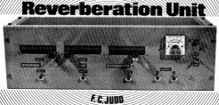
Transistor, voltage drive, HR162 tank, mic and line, VU meter.
Part One
Page
- - Intro, specs, block diagramme
- - Circuit
- - response graphs, signal hookup, internal view
- - metalwork, parts list
- - physical assembly, inside view
Part Two
Page
- - Checking, performance, panel wiring, overload meter
- - circuit layout, power supply, internal view
- - meter marking and response curve, mute
“Vibrato Unit” for use with Electronic Guitars by E.W.Bones
In reality a tremolo or amplitude modulating unit using an EF50 pentode as the modulating element.
Page
- - Introduction
- - circuit
Building your own Electronics Organ by Neville Williams
A valve reverb add-on, published: April 1962.
Page
Delft reverb circuit ideas from Stephen Delft (rough but detailed)
Driver response curve.This is another one that might be worth investigating. This design used a form of current drive similar to Rod Elliot's design.
Most amplifier stages provide constant voltage drive to the load. This is fine when the load is a resistor in the next stage, but the drivers in reverb lines act almost as pure inductances.
That means that their impedance rises steeply with frequency, and if driven from a constant voltage the current, and thus the power, falls off equally quickly.
The engineering response to an inductive load is to drive it with a constant current rather than voltage. This basically means a much higher voltage signal delivered through a largeish resistor, thus approximating a constant current in the load.
While this gives a flatter overall line response, more suitable for Hi-Fi use, we should remember that the traditional reverb circuits of the Dick Dale era were normally voltage drive.
As always it is best to try it in your particular situation and see if it works for you.
|
|