|
http://www.ozvalveamps.org/teisco.html | Created: 21/12/10 | Last update:
04:33 21/12/10
<<< OzValveAmps |
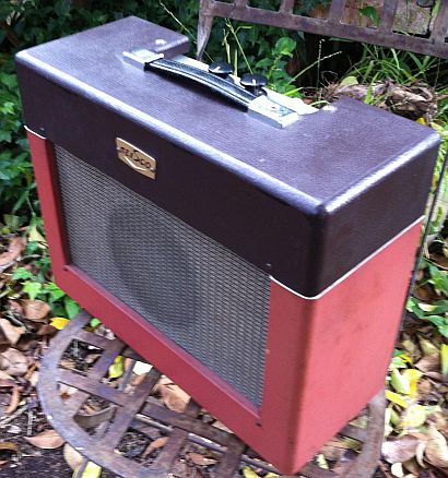
Another example of the many small valve amps that were imported from Japan in the sixies and seventies.
AVA's new Asian Imports Editor, Jeremy Shaw writes...
Hi Roly
One more for the site maybe ?
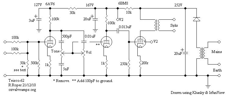
This info is for a Teisco 62 . So a cheap Japanese amp probably 60's, Why am I giving this to the Aussie amp site? Well only because you put a Coltane amp up (Teisco made Coltane and many other brands) + it is a cute little thing. However feel free to not include.
There were two quite odd things going on with this.
1 - It sounded bad at odd positions on volume and tone. On the scope it turned out to have parasitical oscillation , all components checked out ok and sometimes as I tested it would be fine . Worked out eventually that the small capacitance of the scope was enough to get rid of it. Eventually using scope as guide I put a 100pf cap from input of triode section of 6BM
6[8] to ground . This cancelled the oscillation and didn't change the sound. Not sure if this is the usual place to put such but it works a treat and was an easy insert. (feel free to insert criticism here)2 - The grid leak on the input 6AV6 consisted of two resisters in parallel , a 500k and a 50k ?! what with the 100k input resistors, that threw away 2/3 of the signal, to say nothing about low impedance for guitar . It sounded much better (as well as louder) with the 50k removed.
Just thought I send it in as it is probably pretty generic for these simple Japanese amps although this is a 110 volt version with an extra step-
up[down] transformer put in.Suggesting that this one was most likely a single private import and not a significant importer or they would have come with a 240 volt transformer primary.
As always an avid follower of your site, not just for my obsession with old aussie amps but as an informational and educational goldmine. It is remarkable how many times searching the whole web I find the information on your site and sometimes nowhere else !! [It is the users who decide what to submit that directs this site; all circuits, most photos, and a lot of user comments and observations get posted.]
Case in point how to deal with speaker pumping on tremolo. One expert from USA had a little article on how it was a good thing! went on to talk about the doppler effect it gave to the sound due to the changing velocity of speaker. Well maybe but the speaker surely wouldn't like it much. I leave it to your better knowledge to judge if this is as rubbishy as I thought. Also your site (well you) finally explained those networks of resistors and caps around the stage that exits the trem.
Ta again
Jeremy
...
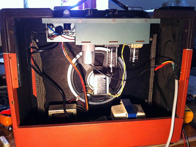
um der the power valve is a 6BM8 not a 6BM6 (head smack) Ps the big round cap in one picture is my 100pf and also a question if I might The cathode resistor of 210 ohm (actually) on pent section of 6BM8 reads 10.5 volt across it at idle I work that out to be 50 miliamp x 252 volts on v1 = 12.6 watt even not counting screen current that seems a lot for a 6BM8 (I think I read 7 watts max) mind you its not red plating or anything and sounds pretty good
Check, check, 1 2 3 ...
The circuit fragment in question;
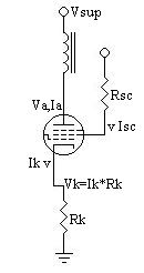 Ik=Ek/Rk 10.5/0.210 = 50mA Pa=Eak*Ia ...(2) Eak = Ea-Ek (ignoring screen current Isc, but subtracting the bias voltage Vk) Pa = (Vsup-Vk)*Ia (strictly Ik = Ia+Isc, but taking Ia ~= Ik) (252-10.5)*.05 = 12.075W (yup, it's cookin') 7 watts desired. To a first *guess* (no data to hand)... Ia=Eak/Pa (transpose (2) above) (252-10.5)/7 = 34.5 mA Rk=Ek/Ik 10.5/0.0345 = 304 ohms (270 or 330 ohms for hot or cold bias) Prk=Ek*Ik 10.7*0.0345 = 0.37watt (1 watt or larger)
If you really want to sort the sheep from the llamas you nead to (very carefully) measure the actual anode current on the hot side. This is best done by securely connecting your meter cold, then powering up for the measurement.
With the output transformer in series we don't want any unexpected breaks in the anode current, might spike the tranny.
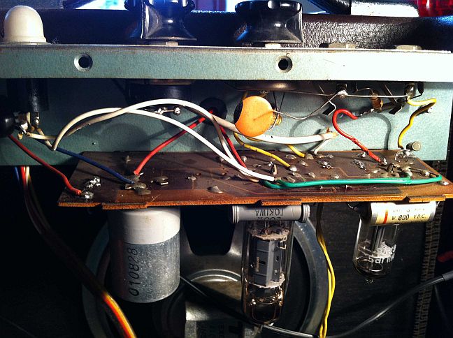
The board and resistors are typical of Japanese amp builds of the era
Traced: Jeremy Shaw
The 50k resistor on the input is original. This strongly suggests that this amp had stability problems in the design phase, and they “fixed” it by slugging the input impedance. This in turn suggests that there may have been something wrong with the PCB layout already in production. This kludge is the sort of thing we see when something has been rushed into production (pressure from upstairs) and important faults slip through the design/test/produce process, and really goo up the works when they come to light in production line testing. It is not unknown for a production line to produce a small mountain of unsalable crap, and somebody has to come up with a way to make them markable, fast. Presto, a 50k resistor across the input, and it still works well enough. -rr
|
|